There is a lot of tweaking that needs to be done once a machine is assembled in order to ensure that it is accurate, reliable, and repeatable. All of the wiring, inputs, and outputs need to be checked, control parameters need to be set, and all of the axes need to be calibrated and squared. Throughout this process the workflow of the machine itself will also be iterated on and validated! This grueling process from first chips to functional machine feels like the home stretch of a marathon, but with a less well-defined finish line!

Checkouts and Parameterization
Electrical Power Checkouts
Before turning anything on it is important to double check the wiring, especially anything power related. Using a voltmeter to check AC phases against each other and ground is a good start. Checking the main DC potentials against each other, DC common, and ground is the next step. Checking the main structure of the machine against ground is a good way to know that all of the metal parts will be safe to touch once power is applied! With everything ringing out fine, it was time to turn off all of the breakers and disconnects, disconnect the fuses, depress the estop, and plug the main power cable into the wall!

With power connected the AC voltage at the disconnect was verified, then the disconnect was closed allowing AC to rush into the cabinet! The voltage on each of the three AC breakers was validated, then the control power breaker was engaged to activate the two control voltage 24V DC power supplies. The DC voltage was verified (there is a trim pot to potentially adjust it) and the DC breaker powering the main controller was engaged – the DDCSE sprang to life for the very first time! The second DC breaker was engaged to power the switches, sensors, relays, and other auxiliary components. So far so good! With the controller powered there was a bunch of parameterization to take care of.
Input and Output Checkouts
The first section I worked through was the IO (inputs and outputs) setup. The IO area of the controller lets you associate different functions of the machine (drive alarms, limit/homing switches, etc) with different input terminals, along with picking their level (normally open vs normally closed). The electrical drawing made this step very easy!

At this point it was easy to validate all of the inputs and outputs because the IO area of the controller has direct feedback on input status and allows you to force the output states. All of the switches were reporting properly and all of the outputs were measured to be activating appropriately!
The only issue found was that the contactor used to drop out the motor power was actually designed for a 24V AC control signal, not a 24V DC control signal. This issue was discovered because of all of the smoke coming out of the contactor’s control coil when it was powered on during the IO checkout! Luckily it was easy to find a 24V DC contactor with approximately the same footprint and swap it out – after that, everything worked.
Axis Parameter Setup
Next came the axis configuration. There are a bunch of parameters related to the pulse train output, master/slave axes, and other mechanical properties of the machine. Additionally, there are a ton of parameters related to the machine dynamics, like maximum velocity and acceleration (and how they might be different in the event of an estop or while in jog mode). The DDCSE manual was surprisingly thorough with its description of all of these parameters, so it was easy to set them to the appropriate value for this machine.

There ended up being a bit of circular logic in the design of the axis drive enable circuit: The controller drops the axis enable signal if it enters an alarm state, but disabling the drives put them in an alarm state that they communicate back to the controller (causing an alarm). The only way to clear the alarm from the drive is to re-enable it … but that can’t be done while the control is in an alarm state! Fancier CNC machines let you customize alarm behavior, or dismiss alarms while they are still active, which might let this design work. However, to make this machine work the drive enable signal was just tied to key ‘K1’ and the controller will no longer automatically disable the drives when alarming (although the E-Stop button still works as expected.)
Before testing the motors while everything is connected to the machine, it is a good idea to test a mechanically disconnected motor to make sure all of the polarities, gains, and scaling factors are in the right ballpark. I hotwired a spare motor into one of the drivers and gave it a quick jog test. It worked!
First Motion
I quickly plugged back in all of the installed motors and prepared for a full test. Turning on the power to the drive motors for the first time was an amazing experience! The contactor gives off a satisfying ‘thunk’ when the e-stop is cleared, the motors make a collective ‘umph’ noise as they draw the rotor into the nearest full step, and the power supplies make a beautiful ‘whirr’ sound as they ramp up to handle the stall current draw.

I started jogging the X axis with the jog rate override turned way down. It was moving (and in the right direction!) I slowly cranked the speed up, testing the limit. Above 5,000mm/min it started to sound kind of funny (and the acceleration was a bit jerky) but the drive didn’t fault until I reached about 8,000mm/min. Not bad!
With the axes moving I confirmed their reasonably jog/rapid/max speeds and updated those parameters. Then I went about confirming the positions of every axis at its positive and negative limit. The limit switches all worked, but they tended to trigger earlier than I had planned. All of the inductive proximity switches being used are triggered from a button head screw, and so to be safe I designed them to trigger when the screw perfectly aligned with the sensor (maximum inductance). However, in reality the switches are triggering from the edge of the button heads and are robbing me of 5mm-10mm of travel distance in every direction (see image of Y axis at negative hard limit below).

Now that all of the axes were configured properly, moving freely and quickly, and were protected by their limit switches I really wanted to cut something! But in order to cut something I first needed to attach a table to the base structure and wire the spindle.
Table Build
The long-term design of this machine involves awesome upgrades like an automatic tool changer and a vacuum table, but as an intermediate step I just want to make a functional flat surface with some T-track so I can start to make things with the router. Because of my extra Y-Axis range of motion, I am able to fit 7 tracks spaced a “metric 5 inches apart” (125mm spacing) which leaves plenty of room to clamp up a full 2×4 project board in between the outer-most tracks.

For the table surface I decided to go with 3/4″ oak plywood instead of the typical 3/4″ MDF because I think it will have much better moisture resistance (from coolant splashes) as well as slightly better stiffness. The obvious downside is that the layered construction will make it a much less homogenous material to flatten with a fly cutter, but I only need to do that once because my intention is to use it as a table surface not a spoil board. I briefly considered HDPE ($300) or even aluminum ($1,750) but I hope this “temporary” table will get upgraded soon so I stuck with the $40 plywood option.
The table mounts to the four main base aluminum T-slot extrusions using M6 screws and T-nuts through counterbored holes in the wood. After ripping my full sheet of plywood in half with a jigsaw, I laid out the position of all of the holes (4 rows of 5 holes) with a sharpie and tape measure. I started by using a spade bit to make the counterbore, with a marker on the bit for me to use as a depth gauge. Afterwards, I was able to use the center mark of the spade bit hole as a guide to run my clearance drill bit through.
Then it was just a matter of dropping in 20 t-nuts and bolting on the table! Squaring up and aligning the table was easy with a tape measure. Later I will want to home and square the axes, set the table position more purposefully, and add the T-Tracks, but for now I just want to cut something!
First Chips
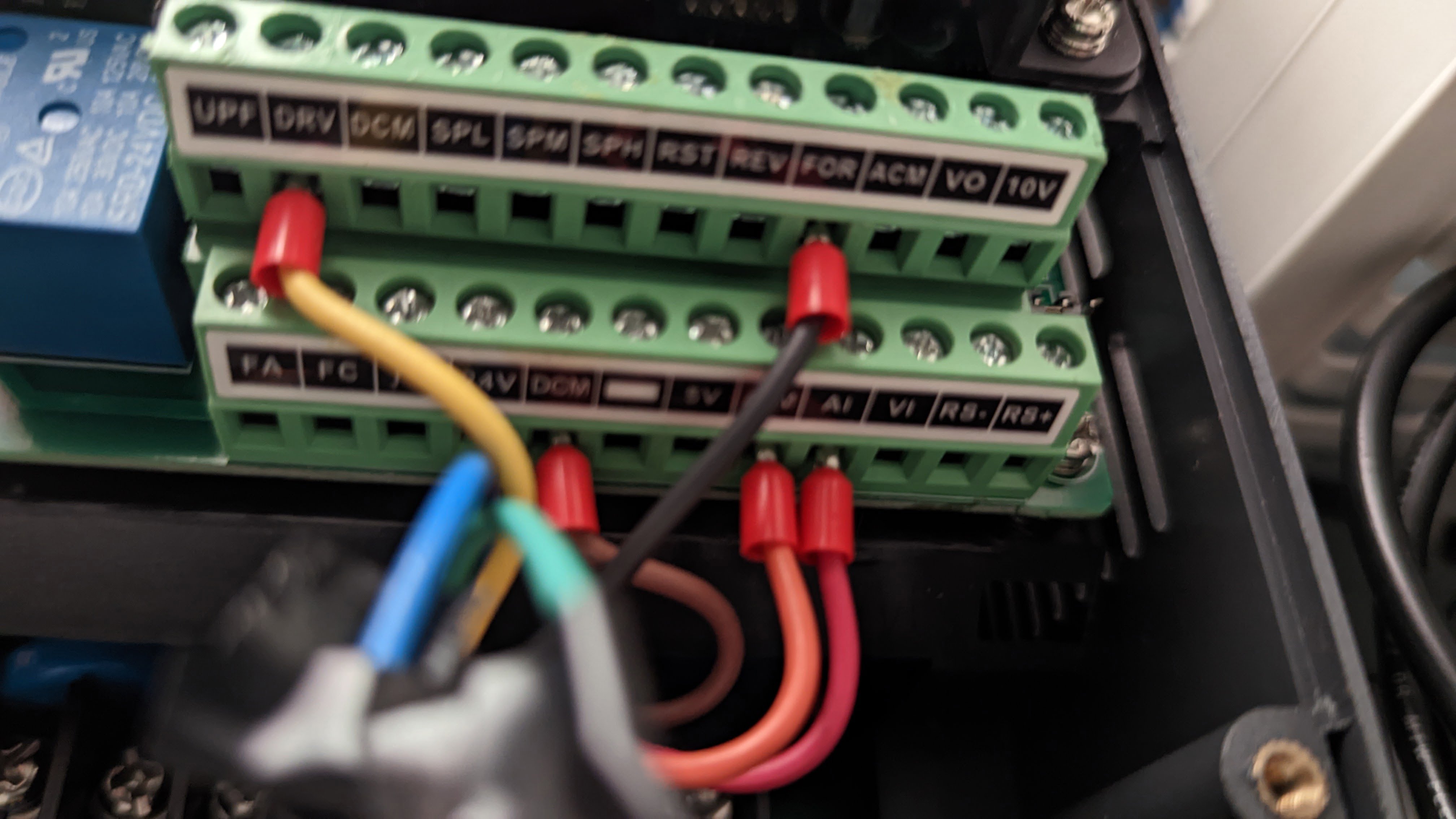
I had left the VFD out of the electrical cabinet at first in order to have better access to other things while commissioning (like the contactor that had to be replaced!). Wiring up the spindle and VFD was straightforward, although soldering the connector at the spindle side was kind of a pain. I scoured the internet for information on how to parameterize the VFD and settled on some values that I thought would work. After entering them into the VFD I commanded a spindle start from the controller…and nothing happened. After poking around and measuring some things I realized that the speed control wire (0-10V) from the controller was connected to the ‘AI’ input on the VFD (for current control, 4-20mA) instead of the ‘VI’ input. I moved one wire, tried again, and the spindle was on!
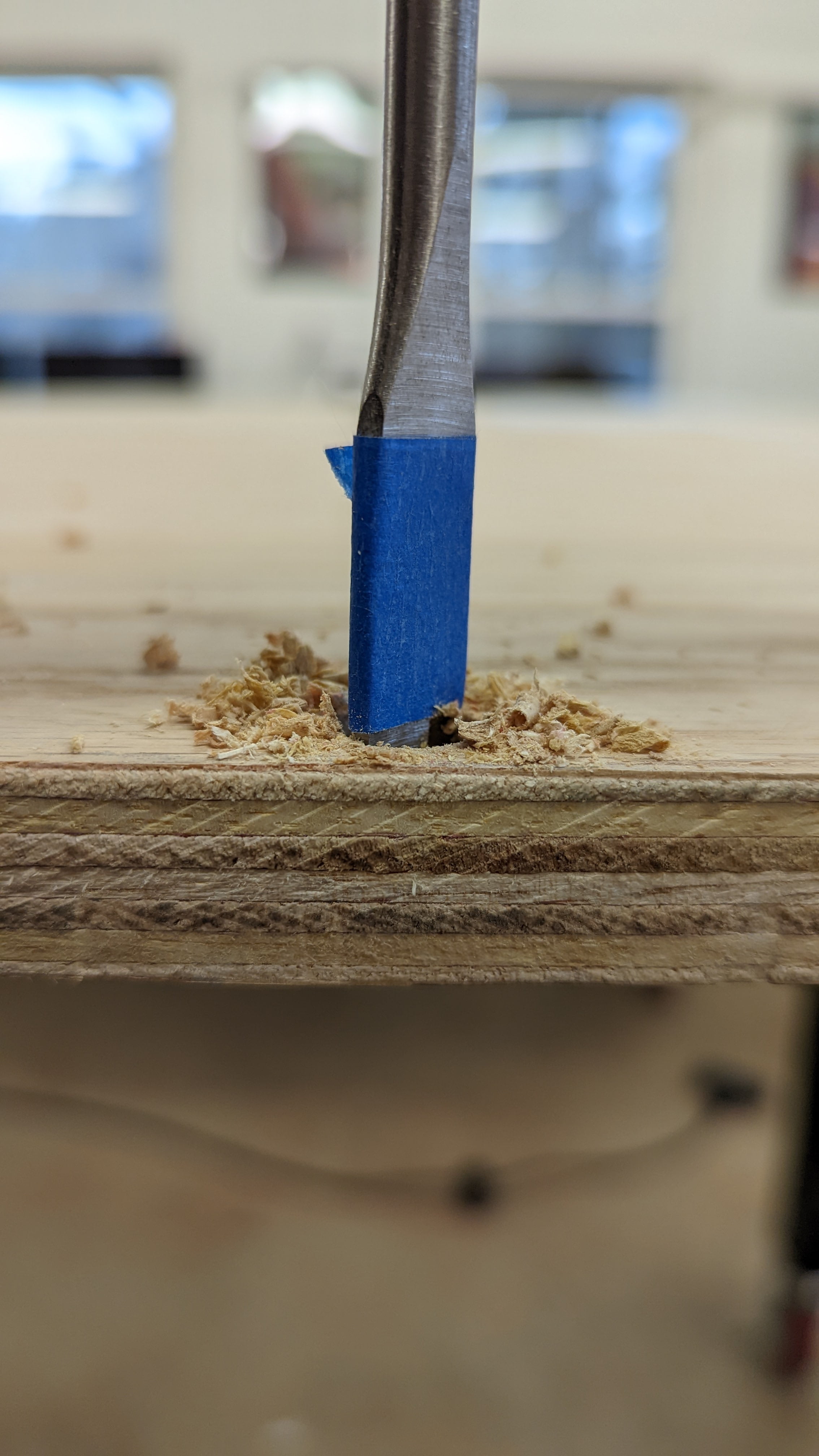
With manual/jog control of the spindle and all the motion axes it was time to finally cut something! I loaded a 1/4″ router bit, clamped a 2×4 to the edge of the table, lined up the depth, and let it rip! I took a pretty beefy first pass by accident, but the machine handled it like a champ!
Well, that was exciting! I’m definitely going to need a dust boot for this thing. But I put a lot of work into making this machine capable of cutting aluminum, so I definitely needed to test that next. I clamped up a scrap piece of aluminum from the router build and lined up the same bit, this time for a 50% width of cut instead of the full 100%. I also slowed down the jog feed and spindle speed a little bit to better match the material.
It made another successful cut, despite the shifty clamp! Doing the math later I backed out a Material Removal Rate (MRR) of about \( 2in^3/min \), which is just over half of the design case. With my reckless urge to cut something satisfied it was time to step back and do some proper machine setup.

Setup and Characterization
Probe Tool
In order to set up the machine I need to be able to measure things: home positions, table positions, workpiece positions, etc. To make this easier it would be nice if the machine could measure itself, so I picked up a touch probe tool.

This touch probe gets routed to an input on the controller and can be used to automatically move (slowly) in one direction until something contacts the probe. At that point, you know where that thing is (assuming that you know where the machine is). But in order to know where the machine is, it needs to have a well-defined origin position and a process for calibrating itself to that origin.
Home Position Calibration
For this machine, the origin is located in the bottom right corner. The X position is defined as the distance (to the right) from the inside plane of the right-side 40160 extrusion to the central axis of the spindle. The Y position is defined as the distance (to the back) from the inside plane of the front 40120 extrusion to the central axis of the spindle. The Z position is defined as the distance (upward) from the upper plane of the front 40120 extrusion to the lower face of the nose of the spindle (without the nut).

This decision was made because these are extremely easy distances to measure. Obviously, the machine can never physically reach its 0,0,0 position but it doesn’t need to! By using the probe tool and precision spacers the spindle can be put in a position with a known offset from the defined home position, then the machine readout can be compared to the known position. I used 1-2-3 blocks as spacers for my setup.
The machine ‘homes’ (sets it machine position reference) using a built-in routine that monitors the homing switches while the axis moves past them. However, the controller needs to know what the ‘actual’ machine position is when the switch is triggered for the process to have any meaning. I put in a good first guess based on the CAD model and ran the routine. Then, I used the probe to measure/reference the physical machine zero and wrote down the difference from my expect values. Finally, I modified the controller’s home switch position parameter to offset it by the error I measured and re-ran the homing routine. When I probed the physical home position again the error was basically gone.
Tramming the Spindle
The next source of error to get rid of is any tilt in the spindle around the X or Y axes – this error can cause unevenness on adjacent planning passes. There are fancy dial indicator setups that can be used to measure spindle tram very accurately, but I couldn’t justify the expense for a measurement I only need to take once. Instead, I put my widest tool (1-1/4″ facing mill) in the spindle and made some test cuts on scrap wood.

I started by making a few passes (using jog mode again) back and forth along the X axis, with a near 100% stepover. I noticed the slightest mismatch in height between the passes (the back side of the intersection was higher than the front side) maybe 0.002″ – 0.003″ (it was hard to pick up with calipers, but it did hang on my fingernail). I added a shim to the top half of the spindle mount (shown below, before I tightened the mount down) to hopefully correct this angle and ran the test again.

I couldn’t see any detectible height mismatch anymore! It’s worth noting that my 1.25″ wide measurement baseline is not nearly large enough for a respectable tram measurement, but I feel confident that I won’t be seeing large mismatches on my 1/4″ and 3/8″ tools if the 1.25″ tool isn’t leaving marks. If I’m wrong, then I’ll just repeat this procedure on aluminum instead of steel to see if that makes a difference.
I set up the scrap board to run tests where I drive the Y axis back and forth to detect issues with tram around the other axis but was unable to detect any mismatch. This is the direction where error is corrected with an eccentric nut, not a shim, and I had already set the spindle and nut based on a bubble level, but I was still surprised to not need any adjustment at all in that axis. Again, I can always repeat the test on aluminum instead of wood if I start having issues in the future.
Flattening the Bed
With the spindle trammed I was ready to use the large fly cutter to machine the wooden table flat. But before I started, I wanted to get a sense of how flat and aligned the top surfaces of the T-Slot extrusion were (noting that I used my work bench to try and align them during assembly) After measuring the top surfaces with the probe tool I was surprised to find almost 1.5mm (0.057″) of variance in height! I narrowed down the problem to two pieces of blocking (shorter extrusions) that snapped into place once I loosened then re-tightened their connecting bolts, along with one end of one of the inner horizontal members (which I negotiated into place with a clamp before re-tightening). These adjustments cut the variance in half, which will hopefully give the plywood a better foundation.

After re-mounting the plywood, I set up my first G-Code program on the machine: a routine to probe the table surface in a 2-inch grid and record the measurements. Just look at that automation! This also gave me a chance to work out the kinks with the network file transfer of gcode files and recorded data.
The initial table probe data was very interesting, with a total variance of about 1mm. There are obviously hot spots associated with the extrusion underneath, but the general left-to-right trend is readily apparent (about 0.3mm/m).

Unfortunately, at this point I had forgotten that I designed the gantry beam to be shimmed at the point where it rests on top of the machine gantry riser plates! A 0.020″ shim on the right side would have killed half of the error immediately! Instead, I preceded to cut away up to 1mm of material with the shell mill (and this time, with a dust boot!)
This was my first machining program on the router and of course I had a few hiccups getting it going (mostly as a result of trying to run a ‘test cut’ above the surface first) which left a gouge in the bottom right of the table. Additionally, by taking such a deep cut I ended up going completely though the top veneer of the plywood, creating abrupt height mismatches where it tore.

After sanding out the work area to smooth over the areas where the veneer tore out, as well as the transition to the front/back of the plywood that were not cut, I took another set of height measurements. The total variance dropped from 1mm to 0.35mm, with a standard deviation of just 0.06mm. I think most of the variance comes from larger negative surface features (torn out veneer) that won’t impact how flat something sits on the table.

Squaring the Gantry
The final adjustment to make is aligning the master and slave Y axes homing positions to make sure that the X axis moves orthogonally to the Y axis. The table itself was squared during assembly using steel cables, so the remaining error is just due to a mismatch in homing positions between the master and slave Y axes. Up to this point I was relying on an initial ‘physical’ alignment I did during assembly where I drove both Y axes against their rear hardstop.
There were a few different gantry squaring programs floating around the DDCSE facebook group, but I ended up writing my own so that I could take advantage of my homing switches (independent of my limit switches). The program basically swaps the master/slave relationship around so that the Y2 axis can home itself in a very normal way against its own limit switch while the Y1 axis follows. Assuming the Y1 axis had already been homed earlier the difference in Y1 and Y2 axis positions is their alignment error, and the Y2 axis can just be moved (independent of the Y1 axis) to match the current position of the Y1 axis.
Of course, this method relies on having accurate homing switch position information stored in the controller! Just like with the initial homing procedure, I started with a good guess in the homing position parameter, then executed the homing procedure and measured the error to feed back into the controller as the ‘real’ parameter value. Measuring the squaring/alignment error ended up being much more involved than writing the squaring program!

To measure the gantry’s squareness, I started by clamping a piece of scrap wood in each corner of the machine. Then I moved to a set of exact coordinates (one in each corner, in what should form a perfect rectangle) and drilled a 1/4″ hole into each piece of wood. Because I have a lot of 1/4″ mill tooling I was able to stick an endmill into each hole to act like a precision pin. With these pins I was able to take two diagonal measurements, which were 1/64th different (+/-0.2mm from their nominal values).
Unlike when I squared the table, I can’t correct this error by directly adjusting a diagonal value. After a little geometry exercise I determined that the Y2 axis was 0.35mm too far ‘back’, so I added 0.35mm to its machine home position parameter and re-ran the squaring program. Afterwards, when I lined up the 1/4″ tool in the spindle above the drilling points on the Y2 side of the machine (using a 1-2-3 block as a reference) I confirmed that it offset in the correct direction and by a very small amount. I’m not super worried about errors at this scale (0.2mm/m) but now is the right time to do the correction if I’ll ever do it at all.
Installing T-Tracks
With a homed, trammed, flattened, and squared machine I could finally use the machine to cut the slots to install the T-tracks! This was going to be my first time using SolidWorks CAM to make gcode for the machine (previous programs were written by hand – luckily, I have a lot of manual gcode experience from my old job!) There were some quirks in the software involving choosing tools, setting up feeds/speeds that were appropriate for wood, and messing with the post-processor to get everything formatted for the DDCSE, but I got through it. I’m still learning and will probably do a deeper dive into the workflow in the future!

The first setup involved using a 1/4″ downcut bit to mill away the 3/4″ wide by 3/8″ deep slots (four width passes and two depth passes). Then in a separate setup, I planned to use a #2 center drill to start/locate the screws. After a few CAM iterations to get the gcode just right to avoid a preprocessing error, the machine was off! This cut was terrifying at first, but I gradually upped the feedrate override from 50% all the way to 100% as I found my courage.
The cuts went well and the dust collection was working fine (for a shop vac.) The larger chunks of wood (non-dust) weren’t really getting sucked in and just kind of got pushed around by the dust boot for a while until the spindle moved on to the next slot. The center drill operation went well enough; I needed to turn off the hard and soft limits on the Z axis to reach all the way down into the slot, and the rapid move into the slot at the beginning almost gave me a heart attack!
Finally, I was able to install the T-Track! I had only machined slots for four tracks, although they were spaced to allow up to seven at some point (they come in 4 packs, but I might decide I want dovetail slots at some point). I had milled 0.010″ extra in depth to ensure that the extrusion didn’t sit proud of the plywood, but I left the width cut at ‘nominal’ to ensure a tight fit.

It took plenty of persuasion from the mallet, but I was able to get all of the slots fully seated eventually. The screws didn’t feel like they were doing much, but they did help sinch down the extrusion in a few spots.
And with that, the machine now ‘works’ and is ready to be used in projects! There are still a few small things (covers, bonus electrical things, other accessories) to add, but none of it will get in the way of operating the machine safely. The first projects might even be making the final few parts for the machine!
My next step is to clean up all of the design files to represent the as-built configuration of the machine and release the first full version of the design on github. I’m also starting to work my way through design, performance, BOM, and assembly documentation for anyone else interested in the project. It’s been a long, steady journey from when I first laid out the requirements 28 months ago and I’m thrilled to have made it to the point where I have a functional machine!
Nice work dude! Very cool to see this coming together. Jealous of that work envelope for sure.
Dude, this is an amazing project in all aspects.
Thanks! I’m finishing up some performance/characterization testing and build/design documentation right now. Hopefully this project ends up being a good resource for other people heading down this path!
looks fantastic. thank you for the documentation. I am interested in 4×8 and helical rack over ball screw.
Were you able to run the feed and speed on your design?
I’ve mostly done wood and plastic, and for those materials everything has worked out as expected. It is always a bit scary at first because the feeds feel way too fast (probably because the RPM is so high) but when I eventually build the courage to bring the feedrate override back to 100% everything is fine.
I also haven’t done any deep slots, but I imagine having a lot of chips build up in a slot and then running them over throws most of my axis/spindle load calculations out the window (especially for aluminum).