Once the general architecture of the CNC has been determined the initial dynamic analysis of each axis can be done. Motors and power transmission components should all be sized just big enough to work together to meet the requirements of the system, but still not destroy the machine in off-nominal load cases.
Spindle Sizing
The spindle is the most power-hungry motor in a CNC router, and is typically the limiting factor for material removal rate. If you are using a standard 110V outlet (potentially on a dedicated circuit in a garage) then your spindle selection will be limited to the 500W-1500W range, but the availability of a 220V circuit can open up much larger spindle options.
At the end of the day maximum material removal rate (volume/time) will be roughly proportional to spindle power in any given material, while tooling and depth of cut choices let you trade axis speed and cutting force proportionally. For materials like wood you can expect a ‘Unit Power’ of around 0.005 \( W / mm^3 / min \), but aluminum will be closer to 0.020 \( W / mm^3 / min \) while steel is much higher still at 0.090 \( W / mm^3 / min \). My understanding is that this difference is roughly driven by the hardness of the material, but investigating it further is a rabbit hole that ends in a PhD five years later.
For a combination wood and aluminum router it seems like a good spindle choice lets you fully utilize the power of the spindle during your most intense wood cutting operations, while not making rough aluminum cutting painfully slow. Spoil board cutting with a shell mill is one of the most intense wood cutting operation I will do. Hard wood and aluminum face milling for bulk material removal are the other processes most limited by the spindle.
Comparing the time it takes to cut a representative feature is a good way to illustrate the diminishing returns that you get from spindle power due to the inverse relationship between power and material removal rate. My representative features are a 0.05″ thick facing operation on a 2′ x 4′ spoil board, and a 6″ x 6″ x 1″ deep pocket in hardwood or aluminum. I can ignore spindle efficiency/utilization for this comparison because it is a linear factor and simply scale the spindle power and representative volume out of each material’s maximum removal rate.
\(Time = \frac{Volume \times UnitPower}{Power} = \frac{Length \times Width \times Thickness \times UnitPower}{Power} \)
| Spindle Power (W) | Spoil Board (min) | Hardwood (min) | Aluminum Pocket (min) | Approximate Cost ($) |
|---|---|---|---|---|
| 500 | 6.4 | 4.0 | 15.9 | $100 |
| 1500 | 3.2 | 2.0 | 8.0 | $250 |
| 2200 | 2.2 | 1.4 | 5.4 | $400 |
| 4000 | 1.2 | 0.7 | 3.0 | $600 |
It’s no surprise that cut time is inversely proportional to spindle power, but the chart really helps you digest how little time savings you get out of drastic (and expensive) increases in spindle power. Moving from 500W to 1500W costs under $200, but saves 3-8 minutes. However, moving from 1500W to 4000W costs over $300, but only saves 2-5 minutes, which is worse bang for your buck!
3 minutes to face a spoil board doesn’t sound bad at all, and running the spindle on a (dedicated) 120V outlet is a huge win for me. A highly utilized production shop would definitely value the investment in a bigger spindle, but for a hobbyist like me 1500W is a good compromise.
Cutting Speed Estimation
The ideal feed rate for a cut is solely determined by the spindle speed, chip load (thickness of material cut by a single flute in a single pass), and flute count. Varying the depth of cut, up to the physical limits of the tool, will alter the amount of power required by the spindle (and feed motors) to execute the cut.
\( FeedRate = FluteCount \times SpindleSpeed \times ChipLoad \)
While there are plenty of “rules of thumb” for determining these numbers, many cutting tool manufacturers will provide this information specifically tuned to their exact tools. In order to figure out the maximum load on the linear axes of the machine for each use case you need to first find a representative tool setup that uses as much of the spindle power as possible.
- Increasing the diameter of a cutting tool will increase the radial depth of cut and axial depth of cut in a given pass, which increases the material removal rate
- Increasing the spindle speed of a cut while maintaining the same desired tooth load requires increasing the feed rate, which increases the material removal rate
- Increasing the tooth load by altering the tool design while maintaining the same desired spindle speed requires increasing the feed rate, which increases the material removal rate
- Increasing the number of cutting surfaces while maintaining the same spindle speed and tooth load requires increasing the feed rate, which increases the material removal rate
The only parameter available to tune by hand is the actual depth of cut. While there is a recommended upper limit on the potential depth of cut for a given tool, the actual depth of cut can be raised slightly or lowered significantly to linearly adjust the amount of power required by the spindle to make the cut. Therefore the strategy for maximizing material removal rate is to find a tool setup that nearly matches the expected continuous power of your spindle, then adjust the depth of cut until the power requirement is achievable.
\(Power = UnitPower \times FeedRate \times CutArea = UnitPower \times FeedRate \times DOC_{Axial} \times DOC_{Radial} \)
Keep in mind that the total available power from the spindle can be reduced from several factors:
- Electrical efficiency
- Mechanical efficiency, such as dull tools
- Factors of safety you may want to apply to ensure hassle-free cuts
- The power curve of the spindle, especially impactful at low RPMs
1.5 kW spindles tend to have ER16 collects, which can hold 3/8″ diameter shanks, at most. I spent hours browsing through the Amana Tools catalogs and plugging numbers into a spreadsheet in order to find a set of tools that I think fit the above strategy.
For this analysis I am assuming 30% RDOC (radial depth of cut) and 100% ADOC (axial depth of cut) for wood and aluminum shoulder milling, while assuming 80% RDOC and 0.05″ ADOC for spoil board removal. Without having a specific spindle in mind I will assume constant power from 12,000 RPM to 24,000 RPM and constant torque below 12,000 RPM. I am targeting between 50% and 75% spindle utilization at full DOC.
| Use Case: | Spoil Board | Hard Wood | Aluminum | Steel |
|---|---|---|---|---|
| Amana Part Number | RC-2248 | 46011 | HSS1638 | 51462 |
| Diameter | 1.5 | 0.375 | 0.3125 | 0.188 |
| Spindle Speed (RPM) | 18,000 | 18,000 | 18,000 | 8200 |
| Cutting Surfaces (#) | 2 | 3 | 2 | 4 |
| Chip Load (in) | 0.0053 | 0.0056 | 0.003 | 0.002 |
| Ideal Feed Rate (in/min) | 191 | 302 | 108 | 66 |
| Max Spindle Power Used (W) | 853 | 950 | 943 | 1025 |
| Spindle Usage Efficiency (%) | 57 | 63 | 63 | 68 |
After finding wood and aluminum cutting tools that meet my criteria, I added steel as an example just for reference. It is wild to see how such a little tool can eat up power so fast because of the significantly larger hardness in the material. The speeds involved are also significantly slower and potentially not very compatible with the style of spindle I intend to integrate. Good thing I’m not planning on cutting any steel…for now!
Cutting Force Estimation
Calculating the exact forces between the tool and the workpiece is another topic worthy of a PhD, but a conservative estimate can be made by assuming that all of the spindle’s torque is exerted as a tangential cutting force at the radius of the tool. With this basic model I can calculate the maximum axis force for the use cases listed above.
With my prior assumption that the spindle would have constant power above 12,000 RPM and constant torque below 12,000 RPM I need to calculate the torque for each relevant spindle speed above 12,000 RPM assuming a maximum 75% spindle utilization. Dividing out the radius of the tool results in my rough force estimate.
\( Torque = \frac{Utilization \times Power}{SpindleSpeed} \)
\( Force = \frac{Torque}{ToolRadius} \)
| Use Case: | Spoil Board | Hard Wood | Aluminum | Steel |
|---|---|---|---|---|
| Feed Rate (IPM) | 191 | 302 | 108 | 66 |
| Spindle Speed (RPM) | 18000 | 18000 | 18000 | 8200 |
| Torque at 100% Power (Nm) | 1.2 | 1.2 | 1.2 | 2.4 |
| Tool Radius (mm) | ||||
| Tangential Force (N) | 63 | 251 | 301 | 1003 |
At this point there are three potential driving load cases:
- High feed rate and medium forces from cutting hard wood
- Medium feed rate and slightly higher forces from cutting aluminum
- Slow feed rate and very high forces from steel
Because steel cutting is not a requirement for this system, and depth of cut can always be reduced to lower the forces involved, it will not be considered. Because power is the product of force and speed I suspect that hardwood cutting will drive motor selection, while aluminum cutting forces will drive frame stiffness and bearing sizing.
Inertial Load Estimation
Inertial loading will be one of the main load cases for the system so estimating the mass of each stage of the system is a necessary first step. The Avid CNC is the closest existing product to what I imagine this design will become, so I will attempt to eyeball the mass of each kinematic component of the Pro 4824 model.

Z Axis Mass: 20kg
- 5 kg from extrusion (10kg/m for 80×160 extrusion)
- 5 kg from motion hardware, NEMA 23 motor, cabling, etc
- 10kg from spindle and mount
X Axis Mass: 15 kg
- 5kg from thick aluminum carriage
- 5kg from motion hardware, cabling, etc
- 5kg for big NEMA 34 motor
Y Axis Mass: 50kg
- 20kg from extrusion (10kg/m for 80×160 extrusion)
- 5 kg from thick aluminum support plates
- 2 x 5 kg from motion hardware, belt reducer/tensioner, cabling, etc on each side
- 2 x 5kg for big NEMA 34 motor
- 5kg from linear rail (1.5kg/m for 20mm HIWIN rail)
Each axis needs to be able to accelerate its own weight and the weight of every axis it supports. Typical accelerations on CNC equipment are around 1G (9.8m/s^2). The Z axis has to fight gravity (which is also 1G) so it must be sized to 2Gs instead of 1! It is then very straightforward to calculate the expected inertial loads on each axis with the target acceleration.
\( InertialLoad = Mass \times Acceleration \)
| Axis | X | Y | Z |
|---|---|---|---|
| Individual Mass (kg) | 15 | 50 | 20 |
| Combined Mass (kg) | 35 | 85 | 20 |
| Target Acceleration (m/s^2) | 10 | 10 | 20 |
| Inertial Load (N) | 350 | 850 | 400 |
Axis Motor Sizing
Based on the worst case combination of loads and speeds on each axis a peak power can be calculated. For this machine, cutting hard wood at max spindle power while accelerating at 1G is the most difficult motor loading event on the X and Y axes. The Z axis doesn’t need to go nearly as fast, and using the same tangential force estimate as the X and Y axes is a conservative upper bound. This is confirmed by adding the inertial load to the hardwood and aluminum cutting load, and multiplying the feed rates in those materials, to find the power required for that use case.
\( Power = Force \times FeedRate \)
| Axis Material | X Wood | X Alum | Y Wood | Y Alum | Z Wood | Z Alum |
|---|---|---|---|---|---|---|
| Worst Case Load (N) | 601 | 651 | 1101 | 1151 | 651 | 701 |
| Feed Rate At Load (in/min) | 302 | 108 | 302 | 108 | 60 | 60 |
| Required Mechanical Power (W) | 77 | 30 | 141 | 53 | 17 | 18 |
As was suspected, high speed hardwood cutting is the driving use case for X/Y axis sizing, but the aluminum case is still relevant for the Z axis. This power should be compared to the “typical” power output of a stepper motor for common frame sizes to get a ballpark estimate. While some fine tuning can be done by selecting motors with specific windings, this comparison (+/- 20% based on motor length) is a great start. I am targeting a factor of safety of about 2 on my stepper motor power sizing because they will be running at 100% duty cycle.
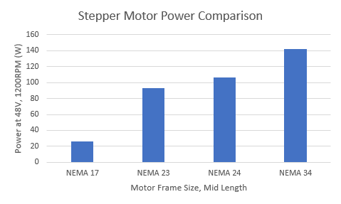
We are clearly in NEMA 34 territory for the X and Y axes (double motor territory on the Y, as was suspected!). The Z Axis is probably going to end up as a NEMA 23 given its power requirement, unless I can think of a good reason for it to move faster than 60IPM under cutting loads (maybe 3D engraving? although acceleration might matter more in that case).
The biggest challenge on the X and Y motors will be ensuring that the motor selected can maintain its power at high RPMs. Hopefully the “gearing” that happens by way of the ball screw pitch lines up the force/speed of the load with the torque/speed capability of the motor. As you can see, the torque on stepper motors falls off dramatically as speed increases, although the total power output of the motor remains relatively constant.
\( Power = Torque \times SpindleSpeed \)

It is ironic that the best way to size a stepper motor that will be used at reasonably high speeds is to shop by power output, yet steppers are typically marketed by peak torque. On the other hand, while spindles are marketed by power output, many high speed engraving spindles are actually constant-torque, only achieving the rated power at their highest speed.
Hello, thank you very much for the informative article. May you please give some calculations (e.g. how you achieved the maximum spindle power in the second table) as I have trouble replicating your calculations. Thanks.
Thanks for reaching out!
The detailed calculations for spindle power under different cutting loads are shown in the “Cutting Cases” tab of the Analysis Excel Workbook on the github repo for this project: https://github.com/burksbuilds/CNC-Router/blob/main/Analysis/Analysis.xlsx
Basically it is just matching up the “Unit Power” of the material being cut (energy it takes to remove a specific volume of material) with the “ideal feeds and speeds” of a given tool in that material.
Hopefully this clarifies my approach for you!
-Andrew
This is awesome stuff. Its pretty rare to see someone uses “old school” hand calc anymore. I truly appreciated this
Any thought about fine tuning the motion profile to optimize the system harmonic?
Old Mechanical Engineer.
I’m glad you appreciated the hand calc approach!
I have not tried to do anything that advanced! I’m just plugging manufacturer numbers into the standard calcs and solidworks CAM. I have not tried cutting steel yet, but I imagine that all of my harmonic gremlins will come out when I do make the attempt.