The spindle and carriage assemblies are each just a machined plate with a bunch of purchased parts bolted to them. The Z Axis rails allow relative motion between the plates, and the clearances on all of the components are extreemly tight! This set of assemblies unveiled more design issues than the rest of the build combined, but in time I was able to work through all of them and mount the final large mechanical assembly to the machine!
Gantry Carriage
The gantry carriage hangs off of the X axis bearing blocks and presents a pair of vertical rails for the Z axis to move on.
Gantry Carriage Plate
Like the gantry riser plates, this plate required multiple setups to machine on my small mill. It has the largest variety of features of any of the four main plates in this project, including a full depth pocket and two perpendicular reference features. There are quite a few M3 threaded holes in this plate, so while the holes are full depth the tapping was only done from the side where threads were necessary.


Gantry Carriage Assembly
Installing the rails onto the plate was about the same process as on the other axes, just shorter. The motion hardware bolted on just fine, but when I went to add the motor I realized I ordered a NEMA 24 but designed around a NEMA 23! Additionally, I thought the flex coupler would be way longer than it actually was. So, I remade the motor mount for a NEMA 24 and drilled new holes to allow the ball screw to shift ‘up’ by about 12mm.
This assembly has a lot of small sections of extrusion bolted to the plate, so I cut them all down to length. Some bolt on to the back of the plate to support the X axis ball nut, while others bolt on to the front in order to ‘seal’ against the Z axis plate.


There are five sensors installed on this assembly (two X axis limit switches on the back, two Z axis limit switches on the front, and the Z axis homing switch on the front). I found out that the Z axis bearing block just barely collides with the Z axis limit switches, but by drilling out the plastic housing on the sensor and shifting it over by 1mm I was able to make everything clear.
Gantry Carriage Mounting
Another 2D 3/8″ plate is used to connect the carriage to the X axis ball nut. The trickiest part about this plate should have been the large clearance hole in the center that I cut out with a boring bar. However, when I went to mount the plate I realized that I left the extra stock from the width of the plate (plate is nominal 100mm wide but I made it from 4″ stock) on the wrong side, which prevented me from bolting it into the carriage! After a quick trim on the bandsaw everything fit up great.


Spindle Carriage
Like the gantry carriage, the spindle carriage is based around a single plate. This plate rides on the Z axis rails and mounts the spindle. Adjustability is built into the spindle mount to allow for easy tramming in two axes.
Spindle Carriage Plate
Unlike the other 3 plates in this design which are kept at stock width, the width of this plate needs to be controlled. That is because it fits snugly between two ‘sealing’ extrusions from the gantry carriage plate in order to try and keep debris out of the interior of the assembly. While it wasn’t pretty, I started by milling my 8″ wide stock plate down to 200mm.
This part has a slight recess machined into most of its back face, with the exception of a tiny strip of material used as a reference edge for the bearing blocks. This was a great opportunity to use the fly cutter! Unfortunately, the channel machined down the middle of the plate was just barely too big to also use the fly cutter in (and has a bump machined into it for mounting the homing switch flag).


This plate also has a bunch of steel threaded inserts smashed into it. These let you unscrew and recrew the spindle mount or nose sealing extender as much as you need without worrying about damaging the threads in the aluminum plate.
Spindle Mount Modifications
These small, 80mm diameter spindles that are common for routers prefer to be mounted by a clamp. There are plenty of off the shelf options, but none of them have integrated features to make tramming easier (like the Avid CNC, they expect to be mounted to a different plate that has those features). Instead, I bought a common cast mount with a blank flange and machined in features for tramming.


In one corner there is a precision hole for rotating around a shoulder bolt and in the opposing corner there is a precision slot to interface with the eccentric bushing. The other two corners have basic clearance holes to secure the mount after the rotation is set.
Spindle Carriage Assembly
The front of the spindle carriage has some small t-tracks for mounting random stuff (like the air nozzle) which had to be prepped. Also, I finally printed all of the limit switch homing flags because the Z axis flag mounts to the back of the spindle plate which will be inaccessible after assembly.


A test fit of the gantry carriage and spindle carriage assemblies on the workbench showed some really tight fits, but everything seemed to slide and mount OK. The gap between the spindle plate and ball nut mount was larger than I expected (I had the wrong ball nut mount modeled) but I was planning on shimming it to fit anyway so I added a thin 3D printed spacer.

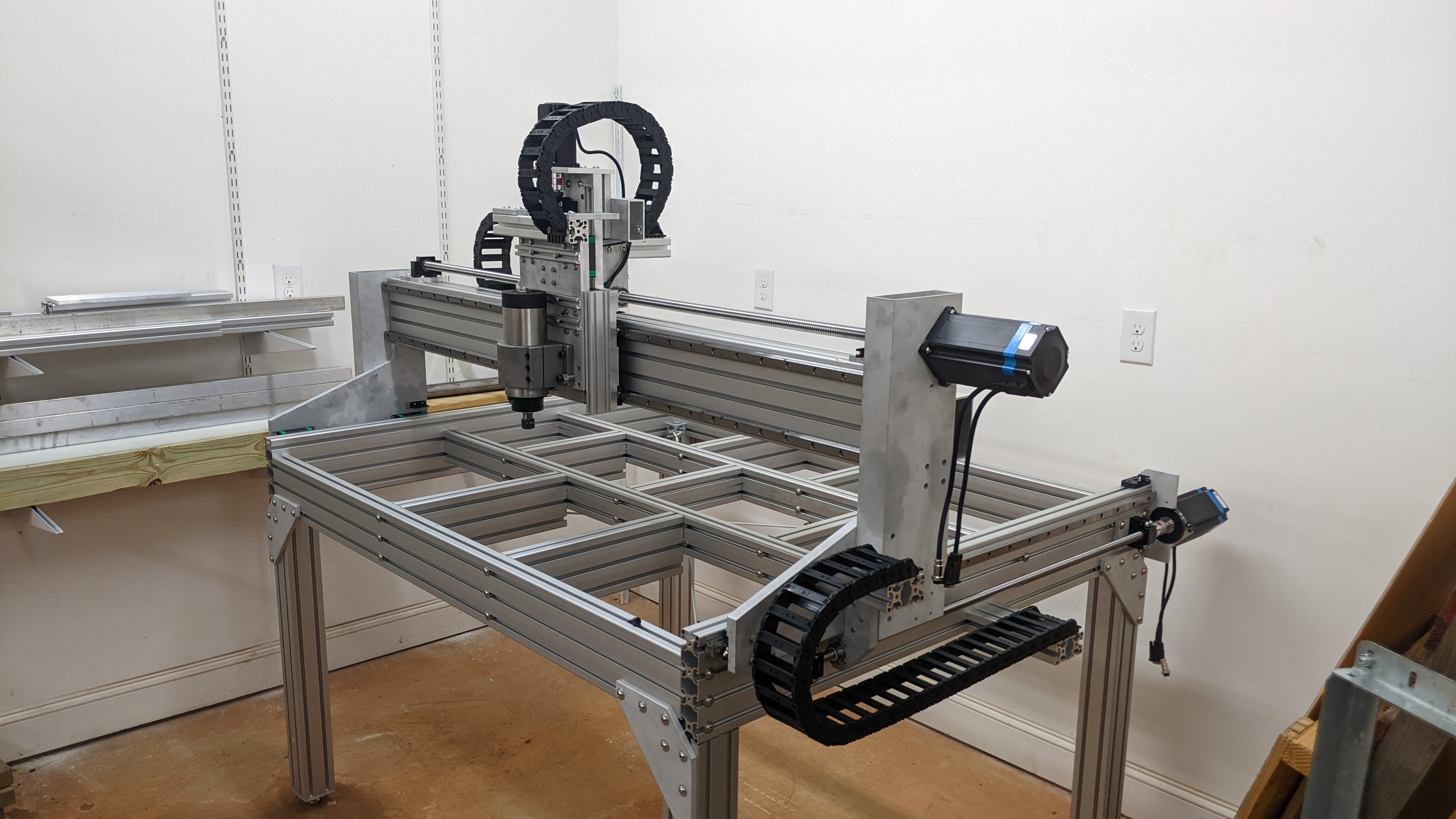
I reassembled everything on the gantry and hooked up the energy chain. The machine looks nearly complete at this point! Unfortunately, there is still a lot of electrical work to do before it starts moving around and cutting anything.
Time and Cost
I logged 11 hours working on the gantry carriage and 10 hours working on the spindle carriage. For both of those assemblies, about 2/3 of the time was spent machining the plate and the rest was spent on assembly. The whole thing bolts together fairly quickly with the rail alignment being the only part that actually takes some time and precision. Obviosuly purchasing the two machined plates would save a ton of time.
The blank for the gantry carriage plate cost $55, while the Z axis rails and ball screw were both $50. Add in another $50 for the small pieces of extrusion and ball nut mount plus $5 in hardware equates to about $210 for the gantry carriage assembly. This does not include the motor and sensors.
The blank for the spindle plate cost just $35 and the spindle clamp cost $35. There is about $25 worth of other plates and extrusion mounted to the plate, but the big cost on this assembly was the hardware. The nine threaded inserts, should bolt, and eccentric nut added $50 on top of the $5 in other assorted hardware. The total mechanical cost for the spindle carriage ended up at $150.
The running cost of the machine is now at $3,085. While this doesn’t include some things in the controls budget (like $172 in cable trays) it is no doubt beating the $5,750 benchmark of the Avid CNC mechanical assembly with leg kit. As detail work on the control system progresses, I worry that it will be difficult to beat the Avid benchmark so easily.