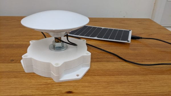
A fixed GNSS RTK base station is used to increase the accuracy of other nearby mobile GNSS receivers to within an inch of their true position (over 100 times better than typical GNSS!). This design expands on the ESP32 + ZEDf9P + RTK2GO combination outlined in this sparkfun guide to include a solar charger, sealed enclosure, and onboard web server. This is the first attempt at a quick design, and is hopefully only one iteration away from the final base station after all the initial lessons are learned. At about $500 this DIY base station is much more affordable than commercial versions.
Problem
On its own basic GNSS (Global Navigation Satellite System, the generic term for GPS and other similar satellite networks) is only accurate to within 20-30 feet. My requirements for the autonomous lawnmower project, and probably other future projects, involve navigational accuracies of about 1 inch. Critically, I only really need this accuracy near my house (not out in the woods like a surveyor, or nationwide like an autonomous car).
Existing Solutions
There are plenty of tricks available for increasing the accuracy of a location estimate:
- Merging the GNSS data with other data sources that have a known location like cell tower signals, wifi signals, and even bluetooth (similar to how your phone works or how stores track you while shopping). Accuracy depends on the prevalence of pre-mapped signals, but tops out at around 2 feet.
- Using higher accuracy GNSS receivers and antennas which support more complex GNSS signals (AKA “L2 Band GNSS”). Accuracy typically in the 1-2 feet range.
- Using the live, calculated position error of a nearby GNSS station to compensate for the measurement of the rover (AKA “Differential GNSS” or “DGNSS”). The correction data can come from a service (some even broadcast over satellites) or provided from a local base station directly. Accuracy typically in the 1-2 feet range.
- In addition to DGNSS, also broadcasting the phase of the GNSS signals received at the base station for the rover to use as additional correction information (AKA “Real Time Kinematic” or “RTK GNSS”. Accuracy typically under 1 inch.
- Similar to RTK GNSS, but instead of using live correction data, raw phase information is recorded and post-processed by a system comprised of a network of base stations monitoring errors in both the atmosphere and the published positions of the satellites themselves (AKA “Precise Point Positioning”). Accuracies well under 1 inch are achievable, but only after post processing.
It seems pretty clear that RTK GNSS is the only option to get highly accurate live position readouts. Unfortunately, this setup involves an expensive L2 band antenna and receiver on both the base station side and the rover side of the correction link. While there are several services that sell you GNSS correction data over the internet or through satellite links, the cost of L2 band electronics has recently come down enough to become accessible by hobbyists (~$350 per setup) which makes building a base station seem much more attractive than paying for data.
It is also encouraging to see that other people working on automated lawnmowers have come to similar conclusions, and their results so far are very promising!
Electrical System
Electrically, the base station is actually fairly simple. The subsystems are:
- GNSS link (antenna and receiver) to capture the GNSS data
- Data link to send correction information to any mobile clients
- Power to support the above two subsystems
Connecting these systems together with a few standard cables (and adding some software!) is all that is required to get a working base station.
GNSS Link
For the base station I chose the sparkfun ZED-F9P breakout because it had an SMA hookup (instead of the fragile UF.L style) and the ease of hookup of the ‘QWIIC’ I2C bus was appealing. Also I couldn’t find any cheaper GNSs boards that support L1/L2 bands and RTCM output data.
Besides L1/L2 support it sounds like the most important aspect of a high accuracy antenna is a good ground plane. For smaller and cheaper antennas you need to supply your own ground plane, but the surveying style antennas include it all in one housing so you don’t have to worry about it. Because errors in the base station will always propagate to every user I decided to splurge and get a nice surveying antenna from sparkfun.
Data Link
Sparkfun has a great project demonstrating how to use the affordable u-blox ZED-F9P chip as a base station. They presented two options for how to broadcast the correction data once the base station is operational:
- Long range serial radio (XBee, LoRa, etc)
- Centralized server (NTRIP caster over WiFi or cellular)
While the long range radio option seems simpler (its basically a direct serial connection) it is likely more power hungry than a WiFi connection. Also, because the correction data is good for up to 5 miles, and still somewhat usable for many miles more, I like the idea of providing that information to the public so anyone else can build off of my base station. While the casting server software is not cheap, there are ‘open’ casters that let you publish and subscribe freely.
Bridging the ZED-F9P GNSS board to WiFi seems like the perfect job for one of the many connected microcontrollers that have become available in recent years. In fact the sparkfun project showed just how easy it is to use one of their ESP32 boards.

Something I have struggled with in the past was getting solid wifi reception on IoT boards. While there is a version of the ESP32 board with a built in antenna I selected the version with a UF.L connector so I could try a few antennas and gauge which one would be best.
Power
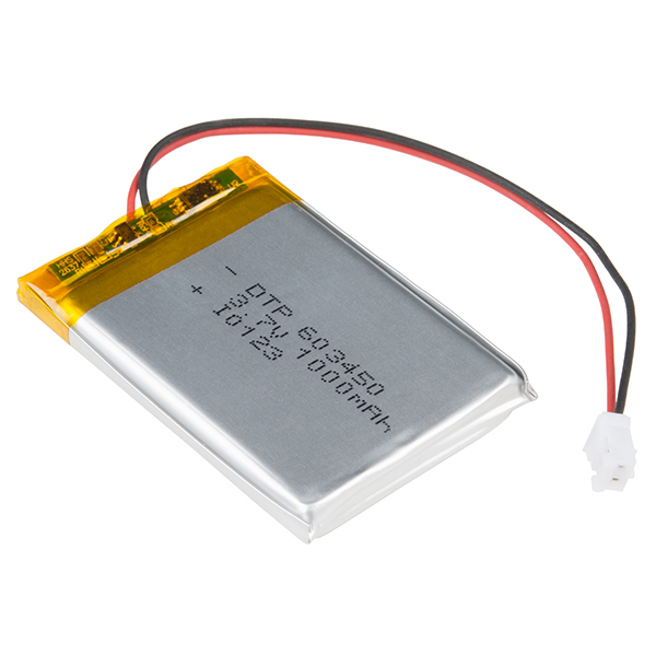
Because this station will live on my roof a completely wireless power option would be idea. Solar power will definitely work during the day, but in order to operate the station at dawn/dusk (evening is probably not necessary) some kind of battery will be necessary. Luckily, the sparkfun ESP32 board from their demo project also has a built in charging circuit that supports single cell LiPo battery packs!
The only clue I have about the total power consumption of the setup is a note from the ESP32 section of the sparkfun project that it consumed about 0.5W. If you assume that you get solar power for half the day, then you need 6Wh of power to carry you through the night. At 3.3V for a LiPo battery, that is just under 2Ah of storage required.
Unfortunately the sparkfun 2Ah battery (largest in the catalog) was out of stock, so I just got the next biggest 1Ah size. In the future, a 3Ah battery might be a better option to carry the station through on cloudy days, but I’ll wait to measure the power draw on my own and order the right battery from somewhere other than sparkfun in the future.
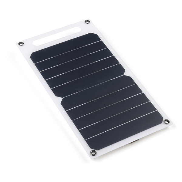
There are plenty of solar panel options for DIY projects, but one particular panel from sparkfun caught my eye because it seemed like it would be incredibly easy to integrate. This panel simply has a USB A port (and presumably an onboard voltage regulator) as the output power interface. This is excellent news because the input power to the rest of the system is through a USB micro port on the ESP32 board (the GNSS board is powered from the ESP32 board over the QWIIC connector). The panel is rated at 10W (and tested to 3W by sparkfun) but I only need about 1W on average. There is a chance this panel won’t survive outside forever, but at just $20 it seems like its worth trying.
Enclosure
There are millions of off the shelf electrical enclosures to choose from. While even cheap plastic ones can have good weather seals, good cable pass throughs are very expensive. My cables are pre-terminated (and I have no interest in trying to terminate coax or USB on my own) which severely limits the options for well sealed pass throughs. All of this drives me to want to build my own simple enclosure for the electronics.
Requirements
The requirements for the enclosure subsystem are:
- Mechanically secure all of the components (and cabling)
- Protect the electronics from the elements
- Provide a mounting point for the antenna
- Provide a mounting point to the roof, or roof mount
The two circuit boards and battery are all very small – less than 2 inches on their longest side. This makes them a great candidate for 3D printing. Because complex geometry is no problem for a 3D printer, I can push the complexity of sealing around the cables onto the enclosure geometry instead of buying expensive cable glands.
I don’t know if extruded filament is watertight, but I’m sure there is some kind of coating I could apply to seal the surface of the printed parts. Joints between parts can easily be sealed with o-rings, while the insulation around the wires can be treated as a similar deformable sealing surface.
While I’ve only ever printed PLA before, it sounds like ASA (“Acrylonitrile Styrene Acrylate”, comparable to ABS) is the best choice for outdoor printed plastics due to its good UV resistance. White colors will reflect the most heat which should keep the electronics cool.
Design
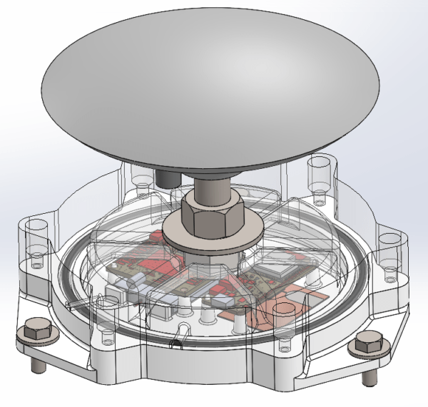
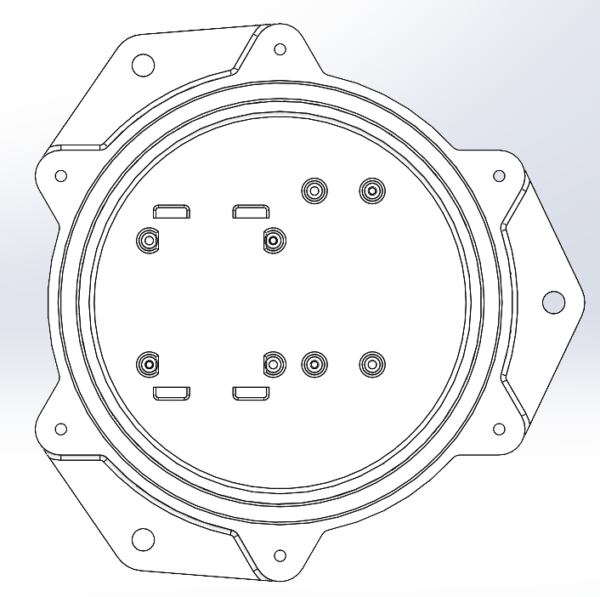
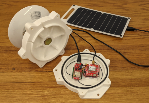
After a few iterations I settled on a two piece design that seals together with an o-ring. I hate dealing with support material so most of the design is optimized around printing the two halves with the outside face-down on the bed, and detailed features ‘growing’ off of the top and bottom inside surfaces.
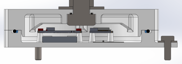
The bottom piece supports two layers of components. The bottom layer has the battery and WiFi antenna, while the top layer has both circuit boards (GNSS and ESP32). The battery ‘snaps’ into a little compartment using bumps on the supports that hold up the GNSS board. The patch antenna has an adhesive back, which is easy (other antenna styles worth testing would require unique mounting features that I don’t want to deal with in the prototype). Both boards are supported by four pillars each – two of them have positive features to locate the board while the other two have a hole so the board can be secured by a screw. I considered making a snap feature for the boards but didn’t want to put the time into dialing in the snap geometry perfectly.
An AS568-250 o-ring sits in the groove surrounding the components on the top surface of the bottom part of the enclosure. Outside of the o-ring are two bolt circles. The inner circle is a pattern of #6 screws to hold the top half of the enclosure against the bottom half while compressing the o-ring (printed at tap diameter, secured with self-threading screws). The outer circle is a pattern of 1/4″ bolts for securing the entire assembly to whatever roof mount is used.
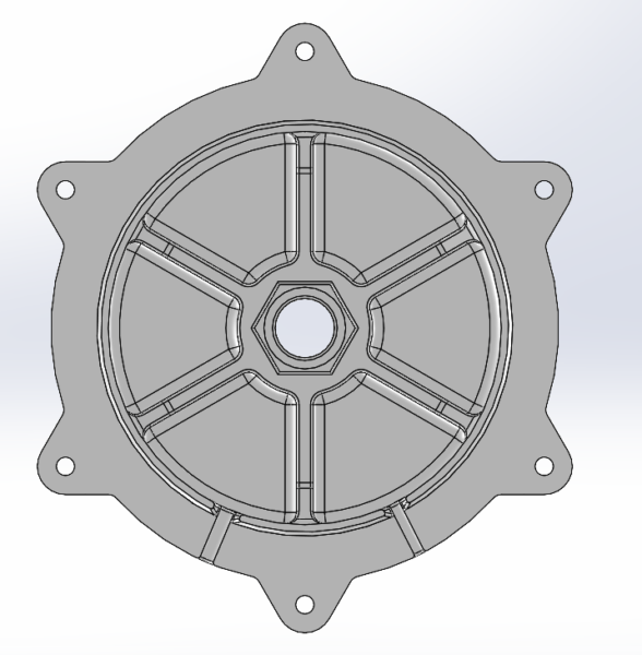
The top half of the enclosure has mating clearance holes for the #6 screws that thread into to the bottom half. There is also a concentric protruding lip with a lead in to line up this half with the other half. In the center of the ‘ceiling’ of the part there is a clearance hold for a 5/8-11 bolt. The head of a hex bolt is constrained from rotating by a negative hex feature in the enclosure, and another smaller o ring is used to seal the hex head against the enclosure. A nut and washer on the outside compress the o-ring and provide a vertical stud for the antenna to mount to.
A pair of arched cut-outs provide a path for the antenna cable and USB cable to exit the enclosure, just above the o-ring. While each cut-out is sized perfectly to fit the cables I am using I don’t expect them to seal perfectly without the addition of some kind of filler goo.
Roof Mount
I have an old ridgeline antenna roof mount kit from when I was beta testing some LEO satellite internet last year. I like this option because it doesn’t involve penetrating your roof to mount the antenna – you simply drape the mount over the ridgeline of your roof and ballast the corners with bricks. Mounting the GNSS antenna enclosure to the main mount point of this roof mount will be no problem, and the solar panel can probably go on some corner somewhere.
Build
Printing the two sides out of PLA was very easy. It definitely helped that I designed them to not need any support material! Assembly was easy enough. Some folds on the LiPo battery corners made it not quite fit into the space I gave it, so in the future I will be sure to leave extra space around the corners. I only had three small screws laying around to secure the electrical boards so I left the corner closest to the USB cable unscrewed because the cable should be held in place really well by the enclosure anyway.
Although I didn’t do any math, it definitely looks like I needed all 6 screws to get enough o-ring compression:


Software
The code for this project is available on github. I’m not proud of it but I learned a lot along the way!
Thankfully sparkfun had already made a great library for communicating with the GNSS board over I2C, so I didn’t have to do anything technical there. The only thing I wanted to do differently from the sparkfun NTRIP server example was to make sure that I could do all of my setup and configuration through the browser instead of over USB because the antenna would be on my roof. This meant that I needed to make three things myself:
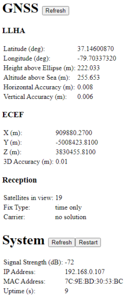
- A self-hosted index page to show me the status of everything on the system (instead of relying on serial printouts)
- A method to set (persistently) various settings like the ‘true’ position of the station and the NTRIP server connection details (instead of hardcoding them)
- A method for downloading hours of raw survey-in data for post processing by a PPP server (instead of connecting to the GNSS board and using u-center)
I wanted to make a super simple index page that wouldn’t require loading any external resources (because it is hosted on the ESP32 and might not be on the internet), but obviously it would need to load its status content dynamically from the ESP32. I also wanted to be able to use the webpage from my phone easily for troubleshooting outside.
To accomplish this I made a few simple GET APIs that return JSON-formatted information about the current position, fix type, uptime, wifi status, etc. Javascript on the index page shoves the data into <td> blocks based on id. Those load scripts run when the page is first loaded, then again anytime you click the refresh buttons. I also added a ‘restart’ API that will reset both the GNSS board and the ESP32 if hit with a POST request.
A pair of GET/POST APIs were made separately for both the fixed position and the NTRIP settings. Internally, these use the ‘Preferences’ feature of the ESP32 (because there is no EEPROM) to store the settings persistently. It was really tricky to get all of the precision properly represented in the internal data structures and as strings because most Arduino libraries don’t support double precision floats, but single precision floats only have ~1m accuracy when representing ECEF coordinates.
Downloading the survey data was the biggest hack in the code. Starting a survey sends a POST command to an API with the duration of the survey as a query parameter. Because the ESP32 cannot store hours and hours of raw GPS data in memory while surveying it needs to live stream data back to the client. The return type from the API is actually a *.ubx file, but sent using ‘chunked’ encoding. This lets me hang in the raw data API handler function, for hours if necessary, slowly writing back raw GPS data as it flows through from a separate process. This blocks all other API calls until the survey is done (which seems fine because surveys are so infrequent).
Overall there are three RTOS tasks running in parallel: the server task, the wifi task, and the GNSS data task. I added some auto-reboot situations to some of the tasks to just restart the whole thing if stuff started to fail (likely because I did something stupid with memory, especially when using the ArduinoJson library!) so I wouldn’t have to climb up onto the roof and mess with stuff.
Prototype Objectives
This is just a prototype, but it is important to go into the design with a list of open questions representing all the gaps in knowledge that prevented me from building a complete design right off the bat. The prototype must be able to answer all of these questions through testing.
- How much power does the GNSS + WiFi system consume?
- How much solar power is available throughout the day, and how much does it vary?
- What kind of antenna will I need to communicate over WiFi from the roof?
- How well can the electronics be sealed from the elements? Is the cable pass through technique used adequate?
- How well will the enclosure stand up to the elements?
- How stable will the roof mount be, especially on windy days? Will it shift over time?
- What kind of tasks will the user want to perform with the system after it is installed? Can the software support all of these tasks?
- How reliable is the software? Can it gracefully recover from faults or outages?
- What kind of accuracy can the antenna survey-in on its own?
- What kind of accuracy can a client achieve using this correction data?



Very cool! What are you hoping to use the RTK corrections for?
I’ll need RTK for the lawnmower, but I can also see myself playing with autonomous watercraft or quadcopters near the house too at some point!
Your method for sending correction data (radio) definitely seems easier to set up than the NTRIP server method I’m using. I’m still struggling to get credentials from RTK2GO.com, and obviously I need to add wifi to everything that gets correction data.
I appreciate how well you documented all of the tweaks you made to your RTK setup to improve the accuracy! That should make my testing run way smoother.