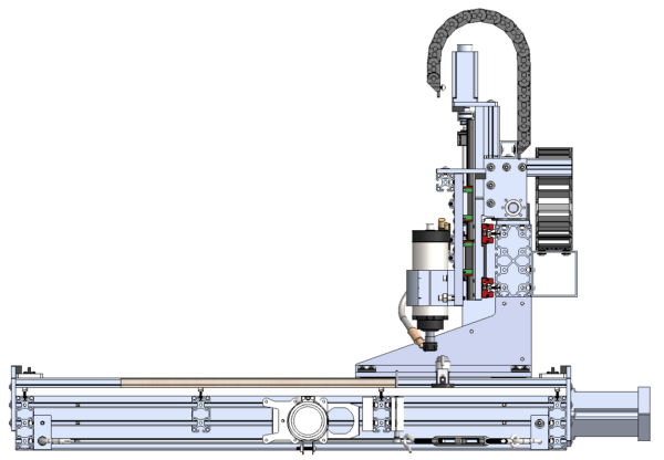
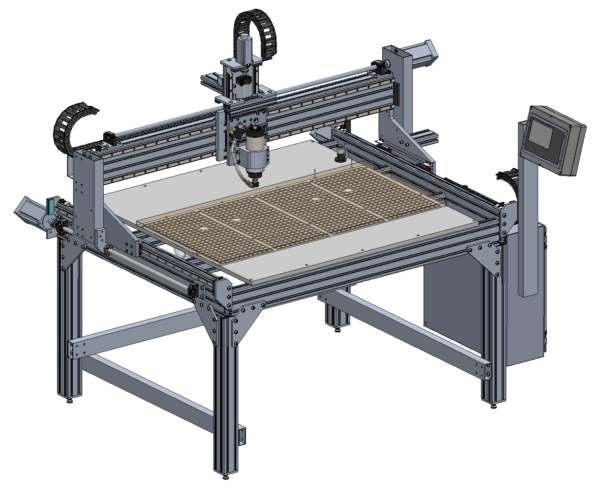
So far most of the engineering and analysis has been done on the moving subassemblies within the router (gantry beam, gantry carriage, spindle carriage). However, the structure that supports all of the moving subassemblies is just as important to the success of the design as the moving assemblies themselves. The frame of the machine needs to support the moving assembly with as little deflection as possible, maintain the squareness of the work surface, and avoiding excess wobbling or walking due to the inertial forces of the cutting head.
Table Squareness and Preload
The main table is approximately 5 feet wide and 4 feet deep, which is much larger than the required 4 x 2 working area. Maintaining parallelism between the two Y axis rails is very important to accuracy and bearing loading. Additionally, maintaining the squareness of the entire parallelogram is important for making accurate, square cuts with the router.
To provide for adjustability of parallelism, the cross pieces will all be cut slightly short and shimmed to length. Because the cross pieces are attached with an axial threaded connection (instead of using T-nuts) the joint can be preloaded and the shims can be easily sandwiched in between the Y axis T slot and the cross pieces.
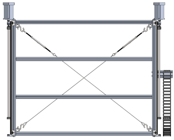
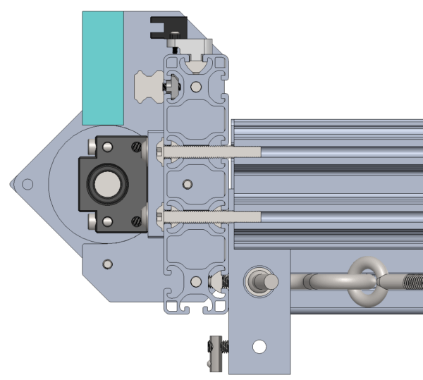
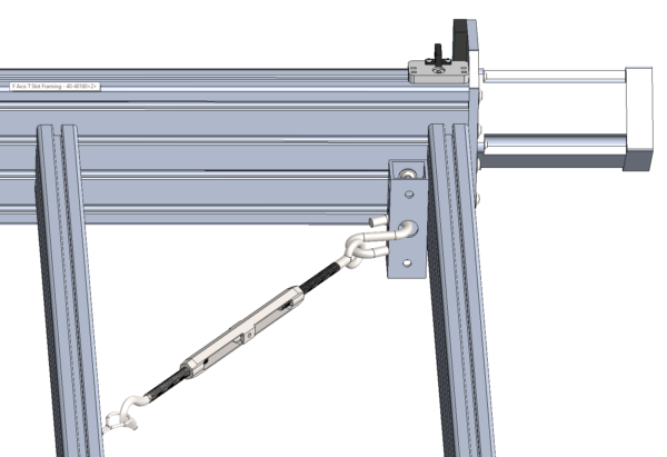
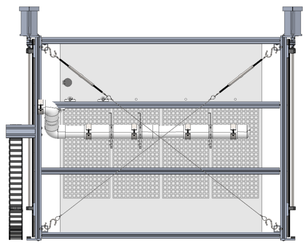
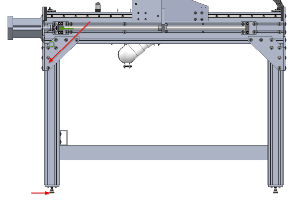
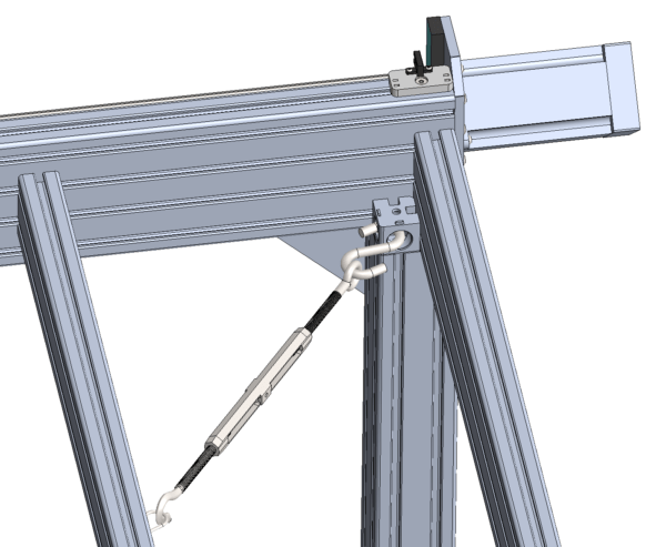
To correct for squareness, as well as apply some additional preload to the entire base, cables are run between opposing corners with a turnbuckle installed to adjust tension. By measuring the diagonal corner distances and adjusting the turnbuckles the entire table can be ‘racked’ side to side as necessary to ensure squareness. This feature is also a good opportunity to provide an attachment point for a potential table leg by extending the corner bracket down.
Table Clamping Options
The exact quantity and positioning of the cross pieces is hard to adjust after building the machine because they are installed using clearance holes in the Y axis rail mounts and shimmed to length, instead of simply being adjusted using T slot connections. To determine the best positioning of the cross members the desired work holding process needs to be evaluated.
Some people like to bolt parts directly to the T-slot cross pieces (like T-tracks in a mill), in which case adding lots of cross members would be beneficial. However, most people tend to use some intermediate continuous table surface (like MDF, HDPE, or metal) with mounting patterns or vacuum features built in. In this case, you need fewer cross members because the table can provide the mounting features and distribute the load back to the cross members.

The Avid CNC instructions have a great page on spoil board options and tradeoffs. Most options only involve adding features within the worktable (dog holes, threaded holes, T slot tracks, mounting holes), usually by using the spindle itself to create them. In those cases, the decision on the exact clamping method can be deferred to later. However, vacuum tables require planning around piping and other infrastructure that must go underneath the table. While I probably won’t add a vacuum table to this router initially, having the option to upgrade later without redoing the entire base is a huge bonus!
Vacuum Table Design
Vacuum tables are useful because the vacuum sucks the entire piece of stock down onto the work surface, using friction to hold it in place. There are no clamps to hit, and with a bleed-through system you can even have a sacrificial table layer for doing through-cuts. Profiling operations can cut all the way through because the small, released pieces will still be sucked down by the vacuum. This convenience comes at the cost of tubing, ducting, and extremely large vacuum pumps. It is extremely convenient for high volume work on large sheets but might not be worth the investment for some hobbyists.
Background

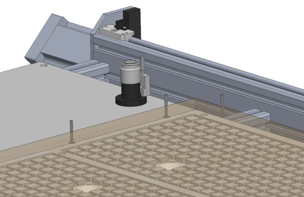
The folks at CNC Cookbook have a lot to say on vacuum table design and are worth checking out. Most vacuum tables are built around cutting a grid of passageways into the top of the ‘plenum board’. A vacuum duct is ported into the bottom of the plenum board, and the suction distributes through the passageways to the entire top surface of the plenum board. By fitting squishy foam cord around the passageways of the loop, a subset of the entire top area can be defined to match the size of the work piece being cut.
Placing a partially permeable ‘bleeder board’, such as MDF, above the plenum board distributes the vacuum even more uniformly. It also provides a cheap, sacrificial layer that can be used when through-cutting.
For large vacuum tables it can be desirable to control which areas of the plenum board are actually receiving vacuum to cut down on lost suction when processing small parts on a large table. Using valves (or cheap blast gates meant for ducting) to isolate the vacuum in these zones is the typical method.
Design Concept
While not a complete design, a rough concept is enough to plan cross member spacing for the initial router build.
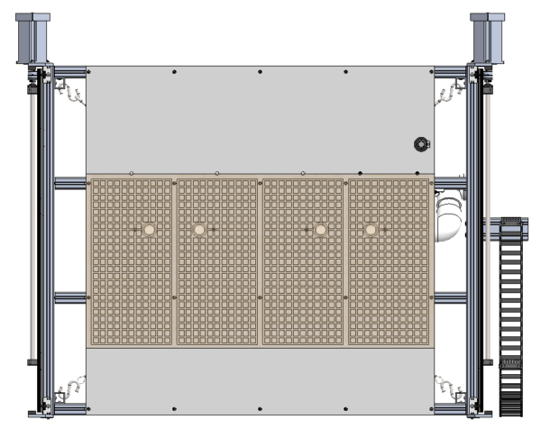
The table concept for this router is based on a 4’x4′ sheet of HDPE or metal (3/4″ thick) to use as the base board / plenum board, which spans all of the cross members. The nominal 2′ x 4′ work area is located at the front most part of the table and contains a bleeder board the same size as the work area. There are a few extra inches of Y axis motion available at the back of the table for a future ATC tool rack and tool length sensor. Additionally, a set of pistons mounted to the rear cross member act as retractable reference pins when pushing material onto the table.
The work area has 4 independent 1′ x 2′ vacuum zones separated by blast gates. I decided to orient the zones vertically to leave open the option of making the table out of four separate plates of material (to avoid shipping a monolithic base board by freight). The downside of this decision is that if I am working on one-foot-wide material that is more than 2 feet in length, I will need to use sealing cord to block off half of each zone. I don’t mind this extra step because by the time I install a vacuum table (and all of the supporting equipment) it implies that I have some parts that I am making at high volumes and won’t need to adjust my setup very often.
Design Implications
The constraints for cross member positioning are:
- Blast gates need room to be in the open or closed positions
- Blast gate frames need to clear the corner tensioning cords
- The rear cross member needs to be located at the back of the work area so the reference piston can be mounted to it
- The work area should be located as far forward as possible to leave room for the ATC tool rack behind it
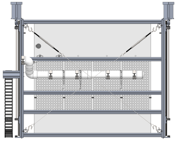
This leaves very little flexibility for the rear cross member, however the decision still remains on whether to cram two cross members into the front of the machine or just stick with a single cross member.
The benefit of the dual cross member option is both the symmetry, as well as the lowered cost ($60) of not having to install the extra cross member. Worktables can be either three or four feet long to fit in the various spans (all by four feet wide). Note that the Avid CNC has a comparable if not larger spacing than this option.
Because of the limited space around the blast gates, the spacing of the back set of cross members only shrinks by two inches if a third cross member is added to the front of the work area. The biggest benefit of this option is that the work area has a cross member at both the front and back edges, which lets you build a full worktable out of only a 2′ x 4′ piece of material. This cost savings is much higher than the price paid for the extra cross member if you use a metal table.
Because I don’t think I’ll ever want a nice metal table surface without covering the entire front part of the machine (to make it easy to slide stuff on and off), I don’t think the third cross member is actually that helpful. I’m going to stick with just two cross members for this build.
Leg Support
This machine has been designed in order to be mounted to any sturdy, horizontal surface. By using a shorter corner bracket configuration, the entire bottom perimeter of t slot can be directly bolted to an existing table. Even the vacuum table plumbing fits between the worktable and mounting table. However, I don’t already have a nice sturdy table to mount this machine to, so I will be building one out of aluminum extrusion.
Corner Gusset Selection
I want to use T slot extrusion for the legs because it should make it easy to gusset the legs into the perimeter T slot on the base of the machine. However, the stringers connecting the bottoms of the legs together would probably be cheaper if they were made out of some kind of aluminum box tube bolted directly to the legs instead of heavier extrusion with external brackets.

My first instinct for the leg gussets was to use a common shelf bracket that you can find at any hardware store. They are large, cheap, and made of steel, which should be plenty stiff. If the gussets on these brackets had a wider cross section then this would probably be true, but all of the ones I found are fairly two dimensional and are extremely likely to buckle.
T slot extrusion is typically braced with either external plates or internal gussets. Stock T slot parts can be very expensive, at about $20 per bracket for the examples linked above. So do I really need a large aluminum bracket, or will the steel shelf bracket be fine?
To analyze the loads in the legs and the gussets I simplified the leg to a beam that was pinned at the connection between the legs and the frame, with a load applied at the foot and reacted by the end of the gusset. The horizontal deceleration load of the gantry or carriage is reacted by the feet, which generated a moment around the pinned leg.
The Y axis direction obviously sees more load because it has to react out the inertial load of the entire gantry (split between the two legs) as well as the carriage (which can be focused on one leg in the worst case). Using the masses developed way back in this post, I can expect the worst-case Y-direction load on a leg to be about 588N. This equates to about 482Nm on the 820mm effective moment arm of the leg.
Depending on the geometry of the gusset being evaluated the loads might be different. The geometry and loads also impact the stress and buckling point of the gusset. I evaluated these cases: the cheap shelving bracket, the standard 1/4″ thick T slot plate, an extended 1/4″ thick t slot plate, and an equivalent 3/8″ thick extended T slot plate (made from the same stock as everything else in this machine).

Both the gusset load and the gusset length are calculated by dividing the axial value over the cosine of the angle of the gusset compared to the horizontal. From there the gusset was just treated as a rectangular beam, with a middle-ground rough-estimate number for width on all of the triangular bits.
The Euler buckling critical load was calculated with \(\pi^2 E I \div k L^2\), where E is elasticity, I is the area moment of inertia, L is the equivalent gusset length, and k represents the loading condition. For a column fixed at both ends (compared to pivoting) a k factor of 0.5 is used. Finally, compressive/tension stress is just calculated as the load divided by the area.
| Shelf Bracket | Standard 1/4″ Plate | Extended 1/4″ Plate | Extended 3/8″ Plate | |
|---|---|---|---|---|
| Equivalent Support Distance (\(mm \) ) | 125 | 60 | 100 | 100 |
| Gusset Load ( \( mm \) ) | 4,454 | 11,364 | 6,818 | 6,818 |
| Gusset Length ( \( mm \) ) | 250 | 85 | 141 | 141 |
| Gusset Area ( \( mm^2 \) ) | 50 | 240 | 480 | 752 |
| Gusset Area Inertia ( \( mm^4 \) ) | 17 | 720 | 1,440 | 5,537 |
| Material Elasticity ( \( MPa \) ) | 200,000 | 70,000 | 70,000 | 70,000 |
| Material Yield Strength ( \( MPa \) ) | 400 | 240 | 240 | 240 |
| Critical Buckling Load ( \( N \) ) | 670 | 88,000 | 63,000 | 141,000 |
| Gusset Stress ( \( MPa \) ) | 77 | 33 | 10 | 6 |
| MOS (FOS 3) Buckling | -0.9 | 1.6 | 2.1 | 10.9 |
| MOS (FOS 3) Yield | 0.7 | 1.4 | 7.0 | 11.5 |
| Cost | $7 | $17 | $20 | $10 |
As suspected, buckling was by far the driving factor in the gusset. Any of the aluminum plate designs are more than adequate for both yield and buckling prevention. While the thin steel shelf gusset was actually strong enough to support the loads, it would almost certainly buckle and force some other piece of hardware closer to the pivot to take up the load, and possibly fail.
Of the remaining options, the Extended 3/8″ plate is the cheapest (assuming the time it takes for you to make it is negligible!) It is also going to be the stiffest option by far because it has both the largest moment arm and the lowest stress.
Stiffness Analysis
Deflection of the legs relative to the base does not have a significant impact on the tool’s performance, but the motion of the tool may resonate with the motion of the table if the natural frequency of the table aligns with the cycle frequency of the tool motion, leading to instability. If the leg/table system has too low of natural frequency then the motions of the tool will need to be artificially limited in order to avoid resonance. 5 Hz is probably a good lower bound for worst case natural frequency, with 10 Hz being preferable. To get a sense of scale, a 1g oscillation at 5Hz is 12mm long, but at 10Hz is only 3mm long.
Given the relationship between stress and strain, it is easy to calculate that the extremely oversized 3/8″ plate only compresses about 0.013 mm when fully loaded. After this motion is amplified at the tip of the leg it has grown to about 0.1 mm. However, this deflection must be added to the deflection along the leg itself, which can be calculated by treating the leg as a cantilevered beam fixed at the end of the gusset and loaded at the foot.
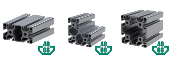
Using a similar method to the gantry beam stiffness analysis in a previous post, the deflection of the leg under max X and max Y axis loading can be calculated. The T slot profiles worth exploring are the 4080 (aligned to support the X axis or Y axis), 408080 (symmetric), and 8080 (symmetric).
For this calculation the Y axis load is 208N and the X axis load is 122N (both per-leg) with a cantilevered length of 720mm. For the purposes of calculating natural frequency only the mass that does not produce an inertial load in that direction is counted. This means that the mass of the Y axis system only includes the base (70kg) and table (80kg, if aluminum) while the X axis also include the mass of the gantry (50kg).
Because all four legs are tied together with stringers, the stiffness from the legs are added together linearly for purposes of calculating natural frequency. In the end, the natural frequency is calculated as \(\sqrt{k/m} \div 2 \pi \), where k is the stiffness of all four legs in one axis and m is the non-inertial load in that direction.
| 4080 X | 4080 Y | 408080 | 8080 | |
| Area Moment of Inertia, X ( \( cm^4 \) ) | 70 | 17 | 120 | 135 |
| Area Moment of Inertia, Y ( \( cm^4 \) ) | 17 | 70 | 120 | 135 |
| Deflection, X ( \( mm \) ) | 0.41 | 1.39 | 0.29 | 0.27 |
| Deflection, Y ( \( mm \) ) | 2.29 | 0.63 | 0.41 | 0.38 |
| Stiffness, X ( \( N/mm \) ) | 1176 | 352 | 1707 | 1832 |
| Stiffness, Y ( \( N/mm \) ) | 364 | 1314 | 2014 | 2191 |
| Natural Frequency, X ( \( Hz \) ) | 12.2 | 6.7 | 14.7 | 15.2 |
| Natural Frequency, Y ( \( Hz \) ) | 7.8 | 14.9 | 18.4 | 19.2 |
| Cost per Leg | $34 | $34 | $63 | $60 |
These are some very interesting results. It was not surprising to see that swapping the orientation of the 4080 extrusions essentially swapped the stiffnesses in the two axes, but it was surprising to see that supporting the X axis resulted in a higher natural frequency than supporting the Y axis, even though supporting the Y axis resulted in lower expected total deflections. This is probably because the X axis has to deal with the extra 50kg of gantry mass in the natural frequency calculation that the Y axis does not need to consider. It is worth noting that the Avid CNC aligns their 4080 legs to support the Y axis (minimize deflections, lower natural frequency).
The 408080 extrusion provides great stiffness in both directions, and packages really well. Unfortunately, it is a fairly rare extrusion profile (I’ve only ever seen it through framing tech) so I would hate to make a design that relies on it. The 8080 profile is just as cheap and just as stiff, but it doesn’t package nearly as well with the existing corner tensioning bracket design. However, substituting a bracket like this would probably make it all work.
After a few small modifications inspired by this analysis the main frame for the CNC router is ready to be built!

