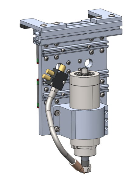
The final mechanical system to design is the mounting structure that attaches the spindle to the 3-Axis motion system. The most important features are the provisions to allow the tramming (slight X/Y tilting) required to align the spindle perpendicularly to the work table. Additionally, the entire vertical gantry needs to support limit switches, cooling, vacuum, potential upgrades (diode laser? larger spindle?), and cabling/tubing for all of the above. Despite requiring all of these features, making the spindle carriage smaller and lighter pays dividends in every other motion stage!
Spindle Tramming
The AVID CNC has an optional tramming kit with instructions for assembly and alignment. They use a fairly common technique involving tramming rotation around the gantry axis with shims, and rotation around the base axis with an eccentric bushing.
The one thing I don’t like about the Avid CNC setup is that it involves 4 pieces of metal riding on the Z axis (base extrusion, tram base plate, tram adjustment plate, and spindle clamp) instead of the theoretical minimum of two. Obviously, this is because they want to be able to sell different configurations of spindles and attachments to a wide base of customers, but the downside is that their highest performance spindle setup involves the heaviest and most complicated mounting package.
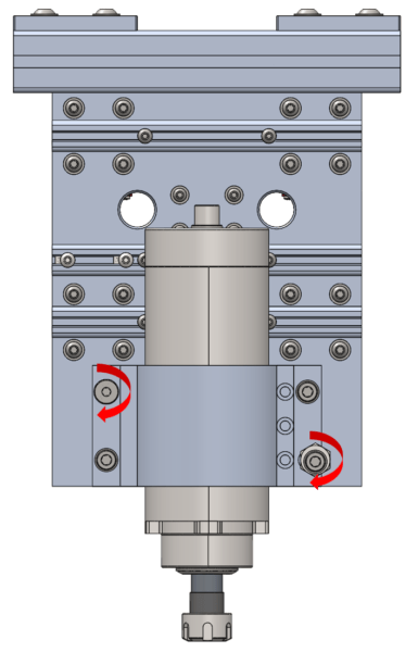
For my spindle I want to use a simple 80mm spindle clamp that can be found anywhere online, but modify the flange to work with the eccentric bushing. By machining a tight-tolerance pivot point in the top-left and slot in the bottom-right of the flange I can achieve one of the degrees of adjustment. The other angle is probably still best adjusted with shims behind the spindle clamp.
Most of this machine is put together with bolts threading into aluminum. If you get enough thread engagement (~2 diameters) and don’t need to assemble/disassemble the joints often, then this kind of joint is sufficient. However, for frequently used joints you really want all of the threads (male and female) to be steel.
In order to accommodate regular re-tramming of the spindle threaded inserts have been designed into the mounting points of the spindle clamp. These are the same inserts used to mount the swivel feet at the bottom of the legs.
Accessory Mounting
There are a few problems with building spindle accessories directly into the carriage plate. One is that I don’t think I know what accessories I really need yet, so I don’t know what hole pattern to add. The bigger problem might be that there are so many bolt heads sticking out of the plate already that there isn’t a great area to mount anything.
The solution I came up with is to just bolt T slots to the spindle plates. The thickness of the T slot extrusion raises the mounting plane above the bolt heads, and the flexibility of the slot allows mounting pretty much any accessory I can find in the future. The particular extrusion I found is a half-sized 2020 from framing tech that works really well.

If you search amazon for cutting coolant misters there are a million versions of the same thing, all with slightly different mounting holes, but all of which can mount to some horizontal T track. Diode lasers also look like they can pretty easily mount to some random horizontal tracks.
The benefit of all of this design work is that the cutting axis of the spindle is less than 6 inches from the mounting face of the gantry rails! This reduces bearing loads and increases stiffness.
Dust Collection
Dust collection is extremely important when cutting wood, and it is best done at the spindle (compared to using an enclosure and flood coolant with metal). There are tons of existing solutions out there, and the best ones all seem to have these features in common:
- Some kind of bracket clamps on to the spindle diameter directly, or occasionally the gantry carriage
- The vacuum hose is suspended from above (not routed through the cable track!) and connected to the bracket
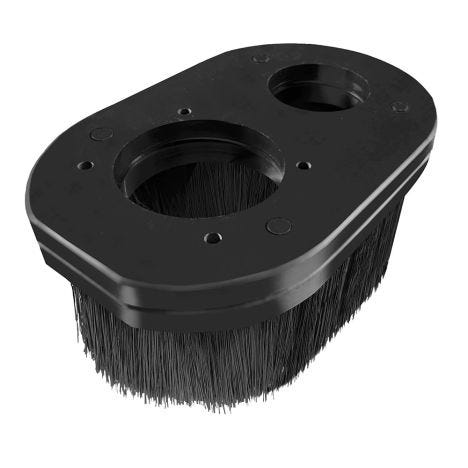
- The dust boot connects to the bottom of the bracket, allowing for different lengths/shapes depending on the job
- The dust boot can get knocked off of the bracket during a collision to avoid direct spindle contact that might require re-alignment

Because there is plenty of room to clamp something on to the bottom of the spindle I don’t have to worry about the specifics of dust collection quite yet. I will likely just pick up an off the shelf option from the internet or 3d print one from grabcad. However, because there are a few dust boots that mount directly to a gantry carriage I thought it would be a good idea to also add some mounting track to that assembly.


