The control system for a CNC router encompasses not only the numeric controller that plans the motions, but also the motor drivers, power supplies, limit switches, circuit protection, and cabling that connect them all together. From voltages to protocols all of these components need to be compatible with each other, which makes control system selection a very wholistic decision.

Component Selection
There are two main directions to go with CNC router controls. One direction is based on common industrial controls, which is characterized by bus-based communication, 24V logic with internal protections, proprietary controllers, great documentation, high reliability, and even higher prices. The other direction is based more on consumer electronics and 3D printers, which is characterized by pulse-based communication, 3.3V-12V logic with few protections, open-sourced controllers, poor documentation, lower reliability, and low prices.
When done right the consumer electronics route can create affordable and reliable machines, but for a one-off project it is easier to throw together common industrial parts and just make it work. The big question to answer for this project is how much extra do you need to pay for the premium experience that comes with industrial controllers?
Spindle Control
Recall that this project is using a common 1500W spindle motor. These motors are speed-controlled using a VFD (Variable Frequency Drive). No matter how the VFD is commanded, it must still output the correct voltage at the correct power level for the spindle motor, along with drawing the correct voltage at the correct phase from the wall. Fortunately, VFD’s are fairly ubiquitous so there are tons of options available.

On the industrial side, many low-end VFDs offer communication card add-ons that allow you to connect them to communication busses like ethernet/IP or Modbus. But almost all VFD’s offer an analog input line (0-10V) for hardware speed control, which is the typical method for inexpensive systems.
Industrial Cost: $250
Consumer Cost: $75
Motor Control
Recall that this project is using large NEMA 34 stepper motors on most axes. Large high-torque stepper motors typically benefit from higher voltage drives (above 48V) because it allows them to maintain full torque at higher speeds. Additionally, using an encoder on the motor allows for slightly higher torque at high speeds, along with feedback to the control system if a step is ever skipped.
The internals and externals of both industrial and low-end stepper drives are fairly similar. There may be some slight performance, efficiency, or noise gains in high-end stepper drives, but overbuilding a cheaper system is more cost effective than getting an extra 5% out of a perfectly sized system if you aren’t worried about heat buildup or power usage.

Industrial drives tend to support protocols like CANopen, Modbus, EtherNet/IP, or even EtherCAT while the low end drives just want step pulses and a direction signal. The biggest downside of the low-end drives is you need some other piece of hardware to generate the high frequency pulses. Additionally, you often get better diagnostic info over a communication bus from the high-end drives compared to a general ‘alarm’ feedback on low end drives.

Industrial Cost: $280
Consumer Cost: $60
Limit Switches
In a previous post small photo interrupters were selected for the limit switches because of their compact size, sensing properties, and low cost. However, like all sensors these switches tend to come in both a PNP and NPN configuration. In Europe and America, most industrial automation digital logic is PNP while Asia has standardized on NPN. Because Asia produces so much of the world’s consumer electronics, the lower-end controllers typically work on and expect to use NPN logic.

This distinction does not impact the choice in industrial vs consumer because the cost and availability of both types of sensors tends to be fairly similar.
Motion Control
More than any other component, the motion controller has the widest array of possible options. This is mostly driven by all of the potential hardware combinations of computer screen + motion controller + pulse generator/bus, some of which might be integrated into one component while others are not.
Some controllers may also be more or less capable of performing secondary functions like managing chillers/compressors, integrating vacuum tables and other work holding actuators, re-squaring a dual-motor gantry, or managing an automated tool change system.
Integrated Industrial Control Panel
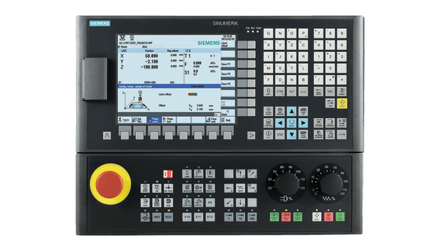
This type of control is the lowest end of the classic industrial controllers. They integrate a low-end PLC into the back of a control panel. All motion control and IO needs to be done over a communication bus. It can do pretty much anything you would want a router to do, thanks to the included programmable logic controller (arbitrary IO logic and handshaking with GCode) and special add-on packages for things like dual-motor gantries.
This kind of system might cost between $2500 and $5000, and it also drives you to use the more expensive VFD and Motor Driver options as well. The manuals and documentation are top notch, but if they ever fail you then you can get an application engineer on the phone who will help you through your problem.
Industrial PC Controller
This type of solution is similar to the integrated industrial control panel, except all of the main features (screen, buttons, and PLC) are built into a standard LCD panel run by a fairly standard PC. Some models even integrate the computer into the monitor to make the device all-in-one.
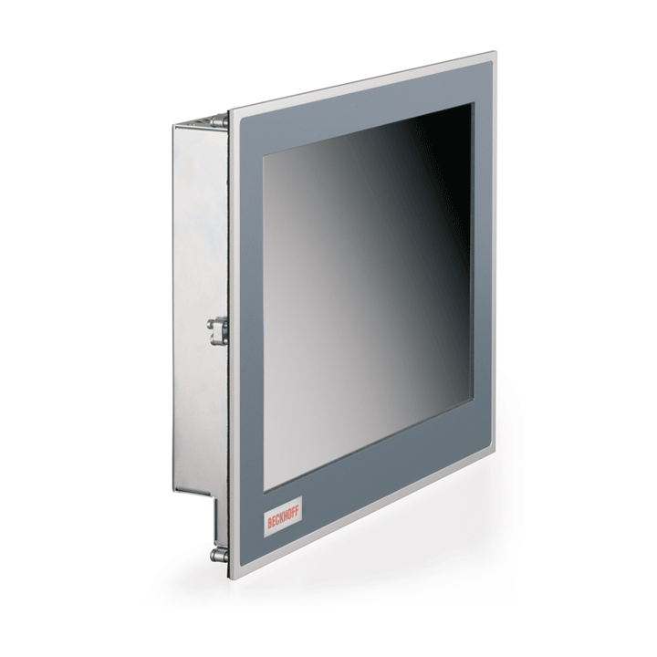
The lack of physical buttons and dials definitely reduces the price, but the experience can be more ‘fiddly’ if you use a mouse+keyboard, and the HMI package might be more work than with the integrated industrial control panel. Use of bus-style motor drivers is required, unless you use bus-style pulse generator IO modules to bridge the gap. The upside is that the price can be as low as $1000 – $2000 for a system, especially if you move away from on-brand hardware.
Integrated Consumer Control Panel
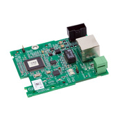
This option is an interesting blend of consumer and industrial. The economies of scale for tablet parts (ARM processors, small LCD screens) and experience from the 3D printer scene have led to many integrated control panels from non-industrial vendors.

The controller can be as simple as some IO plugs connected to a pendant or may include a full panel-mounted control screen. The feature sets can be as simple as running a GCode file from USB or as complex as running probe functions and doing automatic tool changes

While the price of these systems can be a very affordable $200 – $500, they do lack some of the nicer features of more industrial controllers like circuit protection and in-depth documentation. For the more popular brands there is likely a forum or facebook group full of people who can help you work through any problems.
Consumer PC Controller
As you dive deeper into the hobbyist market you find many solutions that revolve around repurposing an old computer to use as the control panel. Most of these systems require some external piece of hardware to generate the pulse/direction signals required by the drives, although some bus-based options (CanOpen and EtherCAT) have started becoming more available and let you skip the extra IO hardware.

LinuxCNC (open source) and Mach3/4 (proprietary) are two popular HMI / GCode interpreter software packages, but they both require a $100-$250 accessory for hardware IO, along with the ‘free’ old computer running the HMI. Setting up that computer to be reliable over long programs (not going to sleep or crashing from some other program) can be tricky.

GRBL is a very popular arduino-based controller. Unlike LinuxCNC and Mach3/4 the arduino actually processes the GCode. While there are some good HMI options available for a connected computer to stream GCode to the arduino, some people have been able to hack together completely ‘headless’ versions where the file is read off of an SD card, for example. There are also versions where an ESP32 is used to enable a web-based HMI. These are hands-down the most affordable controllers at just $50-$100 for the system.
SINGLE Board Controller
There are a bunch of ‘maker boards’ these days that include both a 32 bit ARM computer and a microcontroller or FPGA all on the same board (or in the same chip). There are people from the maker community trying to use the microcontroller as the io hardware board for linuxCNC, which runs on the 32 bit computer. This is a really cool concept with a lot of promise, but there doesn’t seem to be an easy way to make this work quite yet.

Ironically, the integrated consumer control panels actually have a very similar architecture (ARM computer for the HMI, microcontroller or FPGA for the pulse generators). Their higher price point reflects the value they add by integrating all of the components for you, providing limited documentation and support, and adding the screen/housing/terminals.
Power Supplies
It seems like every device wants a different voltage. GRBL boards might run on a 3.3V board. Stepper drives want 5V pulses. Some Linux CNC boards want 12V logic while other more industrial IO wants to use 24V logic. The smaller Z axis motor only needs 48V but the larger motors all could benefit from 72V.
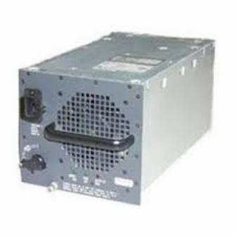
The printNC website has a whole page dedicated to this problem, and generally suggests using old server power supplies to manage it. These power supplies support low currents at various low DC voltages, but also have a large current output at higher DC voltages for the motors.
One benefit of using more industrial equipment is that the power supply requirements are simplified. Everything typically wants 24V for logic, and some multiple of 24V for muscle. Stacking a few beefy 24V power supplies in series lets you power the big motors, while tapping off 24V from the bottom of the stack for your logic.
System Selection
Making an Industrial or Consumer PC controller is a tempting option. The biggest negative is coming up with a clean way to get step/direction signals out of the PC or paying the premium for connected drives. In the end it seems like more work and more money than other options on the list, although it might end up being more customizable and configurable in the end if I have the patience.
Overall I think the best option for the type of machine I am trying to build involves a consumer integrated control panel. It is compatible with the inexpensive motor drivers and VFDs, but still acts as a plug-and-play system. By pretending to be an industrial system it provides 24V logic level support that makes power distribution easier and has screw terminals for all hookups instead of solder points. The biggest drawback is the lack of dual motor gantry squaring in most of these models, although everyone on the forums is constantly telling me I “don’t need it”.
At the low end of the spectrum, the integrated control panels simply send pulse/direction signals to motor drivers and provide homing switch inputs. In the middle of the spectrum, they provide outputs for coolant/vacuum on/off, and inputs for some limit or homing switches. At the top end of the spectrum these systems also include alarm inputs and auxiliary outputs (for processes like tool changes).
Personally, I think features like drive/VFD alarm feedback and limit switches on every axis are what sperate machines that ‘just work’ from the machines that end up becoming a project every time you want to use them. Mostly this is because the controller is capable of telling the operator what is wrong instead of forcing the operator to poke around with a multimeter testing IO.
The specific components I dug up that I want to use are:
- DDCS Expert control panel from DDCNC, with MPG (pendant)
- CL86T Closed Loop Stepper Driver from OMC-StepperOnline (mostly because I had some on hand) (x4)
- HuanYang VFD or similar. As long as it has a fault output
- Meanwell SE-600 24 (x3) for motor power
- Meanwell EDR-150-24 (x2) for control and IO power
Component Packaging
Typically, the size and shape of electronic components don’t impact the overall architecture of a system, but they do matter in a few places. Wire and cable routing is an often-overlooked constraint, especially across joints. Drag chains need to be sized to accommodate all of the cables and tubing that need to make it from one axis to another.
Additionally, all of the primary electrical components (power supplies, motor drivers, VFDs) need to be placed in a protective enclosure where they can blow air everywhere to regulate their temperature without getting covered in chips and sawdust! Fitting these big boxes into an enclosure, with adequate space for routing and a plan for entry/exit points should be verified before the mechanical design is finalized.
Finally, plans for future expansion need to be considered to avoid having to completely replace drag chains or electrical enclosures when some new feature is added. This particular machine may one day add a rotary axis, upgrade to a higher-powered water-cooled spindle, incorporate a vacuum table for work holding, or integrate an automatic tool changer.
Drag Chains
Igus is without a doubt the leading energy chain vendor because of their acceptable prices, good products, and great documentation. There are some cheaper options available from no-name vendors but using the Igus configuration tools for planning and CAD models for reference is a no brainer.
The E2 product line from Igus has cable carriers in about the right size. The 1500 series opens on the outer radius, which I think is convenient. It has a selectable inner width (steps between 15mm and 80mm), and inner height (steps between 21 and 45mm).
Bend radius of the E-Chain is driven by the largest cable in the track, which is definitely going to be the spindle cable. Based on the datasheet for a representative cable, a 125mm bend radius (12.5 x diameter) in the E-chain is appropriate, although choosing the 100mm bend radius E-chain and biasing the spindle cable to the outside might be sufficient. A tighter bend radius on the cable might be possible with other more expensive insulation types, but a 100mm bend radius E-chain seems to package really well in a few places.
Choosing the smallest inner height you can get away with is typically a good idea, because it reduces rubbing between cables when they go around a bend. because the largest cable in this bundle is only 10mm, the 21mm inner height option should be plenty big.

Although the Igus packing tool is handy, I prefer to use a separate tool to track E-chain packing so that it can maintain synchronization with the electrical drawing. It also lets me differentiate between items that are definitely going in the chain compared to items that might be part of a future upgrade (like a water-cooled spindle or ATC). Here is a diagram of the Y axis E-chain, which contains the most cables and tubes by far.

Separating motor cables from signal cables is always a good idea for reducing noise and interference, even if the motor cables are shielded. In this diagram I use the center of the chain to hold pneumatic (and maybe coolant) lines, providing maximum separation.
The X Axis motor, encoder, and limit switch cables drop out but everything else continues into the X Axis E-Chain. This uses the same chain profile, but it slightly less filled than the Y axis. Over-filled E-Chains are a huge pain, so I want to err on the side of too much room than too little, especially for a price difference of only $1/ft.

The Z Axis motor and encoder cables drop out and everything else continues into the Z Axis E-Chain. At this point I feel comfortable dropping the chain width down one notch, even though the cavity dedicated to tubes hasn’t lost a single item.

The final piece of the puzzle is choosing a mounting strategy. There are brackets available for bolting the end of the E-Chain on its inner profile or outer profile, including features for strain relief. These brackets use M6 flat heads, so they are very easy to bolt into 40mm T slot framing or rivet nuts.

Enclosure
Real electrical enclosures can be expensive when purchased new, and even more expensive to ship (as large steel objects). However, there are always tons of used enclosures available from old equipment, and a nearby option might not be too pricey to ship.

While most medium sized electrical enclosures are boring wall-mounted rectangles, console style enclosures offer a fun combination of HMI mounting point and electrical box. Unfortunately, the easy to find ‘consolet‘ style enclosures are too small to hold everything a router needs, and the larger style console enclosures aren’t as widely available on the used market.
The control panel is meant to get mounted to an enclosure door, but to keep it in a convenient location for the operator it will likely end up in a separate, much smaller box than the main control box. The notional plan is to connect the HMI box to the main box with an aluminum tube and run cables inside the tube.

While the final enclosure layout depends on a lot of small details that aren’t designed yet, a rough box sizing can be done by just laying out the larger components on a grid. For this project, a 24″ x 24″ electrical enclosure looks to be about the right size. These can be found on ebay for under $200.

In this design, 240VAC comes in at the bottom right and gets filtered/protected/distributed to the VFD and power supplies. The signals from the control panel come in at the top left and are either routed to the stepper drives (top right) directly or landed on terminals in the top left. Spindle and motor cables leave the box at an opening in the center right of the box, while encoder and signal cables leave the box at the top right.

The control cabinet seems to fit really well under the Y axis E-Chain. I really like this location because it not only gives the chain the support it needs, but it also provides a good visual indication of the space occupied by the things that stick out from the gantry (like the X axis motor). The top of the box can easily be mounted directly into the bottom row of T-slots from the base structure. Once some kind of leg support system is added the bottom of the box can probably secured to that as well.