Stiffness is possibly the most important characteristic of a machine tool. It not only impacts toolpath accuracy (because the tool and machine deflect under the cutting load and acceleration) but also the surface finish, cut quality, and motion control stability due to the interaction between spindle speed and natural resonances. Up until now I’ve only been driving stiffness into my machine design through hunches and best practices. This post will cover a simplified stiffness and natural frequency analysis of the CNC router.
Analysis Strategy
Stiffness is simply the relationship, often linear, between the force in an object and the deflection of that object. For a simple coil spring with one dimension of deflection the linear relationship is true even for somewhat large deflections. However, for a complicated shape (like an entire CNC router) representing ‘stiffness’ with just one parameter is not possible. Both the problem and the model need to be simplified in order to get a more useful result.
The approach I am taking is to calculate the deflection of the tool at a few worst case or important load conditions (maximum speed/load in cardinal directions, as well as a ‘typical’ finish pass). The calculated deflection can determine the absolute profile error due to deflection for the given cut case, but can also be combined with the applied load to generate an approximate ‘stiffness’ for each load case.
The X axis gantry beam, despite being a 80mm x 160mm extrusion, has the worst aspect ratio of any load bearing member in the design due to its 1600mm length. Compared to the Y axis base, which can be firmly secured to a table or shear plate, and the Z axis plates, which transfer load directly through stacks of bearing blocks when in their lowered position, the X axis gantry will see the most deflection in the system.
Gantry Spreadsheet Analysis
While I could shove my model into an FEA program and get some deflection results right away, I always prefer to start with hand calculations in a spreadsheet to give me a better understanding of how the inputs to the system (lengths, thicknesses, loads) impact the output that I am trying to optimize.
Load Cases
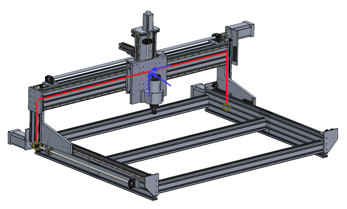
For my spreadsheet analysis I will model the gantry risers (small T slot extrusion on Y axis bearing plates) as one beam, and the gantry itself as another. I assume that the gantry risers are fixed at the bottom where the bearings attach and that the loads (forces and moments) calculated for the X axis bearings are being applied at a point in the center of the gantry beam. The load cases I am most interested in are tabulated below:
| X Axis Cut | Y Axis Cut | X/Y Combo Cut | Finish Pass | |
|---|---|---|---|---|
| X Force (N) | 650 | 350 | 500 | 130 |
| Y Force (N) | 350 | 650 | 500 | 130 |
| Z Force (N) | 700 | 700 | 700 | 140 |
| X Moment (Nm) | 59 | 193 | 126 | 39 |
| Y Moment (Nm) | 129 | 5 | 66 | 26 |
| Z Moment (Nm) | 77 | 32 | 54 | 15 |
Each of the six input loads impacts the final tool position in a number of ways, based on different methods of modeling the gantry beam and risers as simple beams:
- X Axis Force:
- Compresses the gantry beam, which is negligible because aluminum is very stiff in pure compression/extension
- ‘Racks’ the entire gantry frame by bending the risers as if they were a cantilevered beam, translating the entire tool in the X axis
- Y Axis Force:
- Bends the gantry beam like a center-loaded simply supported beam, translating the entire tool in the Y axis
- Twists the riser beam like a torsion load, which can be ignored if the gantry beam model allows for deflection at the ends
- Z Axis Force:
- Bends the gantry beam like a center-loaded simply supported beam, translating the entire tool in the Z axis
- Bends the riser beam like a moment-loaded cantilevered beam, which can be ignored if the gantry beam model allowed for deflection at the ends
- X Axis Moment:
- Twists the gantry beam like a torsion load, which can be modeled on one half as a cantilever rod in torsion due to the symmetry of the setup, resulting in both Y and Z axis deflections at the tool due to rotation about the X axis
- Y Axis Moment:
- Bends the gantry beam like an S, which can be modeled on one half as a cantilever beam with a moment load due to the symmetry of the setup, resulting in both X and Z deflections at the tool due to rotation about the Y axis, although the Z axis deflection is negligible due to cosine error
- Z Axis Moment:
- Bends the gantry beam like an S, which can be modeled on one half as a cantilever beam with a moment load due to the symmetry of the setup, resulting in both X and Y deflections at the tool due to rotation about the Z axis, although the Y axis deflection is negligible due to cosine error
Modeling
For the beams in bending the two important pieces of information to look up or calculate are the area moment of inertia of the cross section of the beam, along with the modulus of elasticity for the material (aluminum in this case) of the beam. For beams in torsion two similar properties are required: The polar moment of inertia of the cross section of the beam along with the modulus or rigidity (also known as shear modulus) of the material.
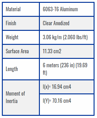
Luckily, extrusion vendors like Misumi and Framing Tech often list the area moment of inertia for their profiles right on their website! Unfortunately, they do not list the polar moment of inertia so it needs to be calculated or approximated. One way would be to approximate the t slot extrusion as a box beam or some other simple shape with a calculable inertia. However, Solidworks has a feature that automatically calculates all three inertias for a given cross section, and they seem to line up with the vendor numbers fairly well (which is no surprise, because I downloaded this model from FramingTech!):

The riser beam is a special case of a composite beam profile where the t-slot extrusion is bolted to a solid aluminum plate. Using standard formulas the area moment of inertia of the aluminum plate can be determined. Before combining the two inertias with addition they must be offset from the composite bending plane (in this case probably the interface between the two parts) using the parallel axis theorem.
\(I_{offset} = I + A (l_{offset})^2\)
| Property | Value |
|---|---|
| Area Inertia of Extrusion Individually (\(cm^4\)) | 16.9 |
| Area Inertia of Extrusion, Offset (\(cm^4\)) | 48.6 |
| Area Inertia of Plate Individually (\(cm^4\)) | 4.6 |
| Area Inertia of Plate, Offset (\(cm^4\)) | 18.3 |
| Area Inertia of Entire Riser Combined (\(cm^4\)) | 66.9 |
It is pretty clear that adding the extra piece of extrusion to the outside of the riser plate had the intended effect of dramatically increasing stiffness in the X axis. The inertia increased by a full order of magnitude compared to just the plate by itself!
The modulus for most aluminums will be fairly similar (even if properties like strength will vary widely based on temper). I used matweb to check the modulus of elasticity and shear modulus of the 6063-T6 aluminum that FramingTech uses for their extrusion.
In summary, here are the properties of the two beams being modeled:
| Property | Symbol | Value |
|---|---|---|
| Gantry Area Inertia, Z Axis (\(cm^4\)) | \(I_{GB_Z}\) | 266 |
| Gantry Area Inertia, Y Axis (\(cm^4\)) | \(I_{GB_Y}\) | 904 |
| Gantry Polar Inertia, X Axis (\(cm^4\)) | \(J_{GB_X}\) | 1170 |
| Riser Area Inertia, Y Axis (\(cm^4\)) | \(I_{GR_Y}\) | 67 |
| Modulus of Elasticity (\(N/mm^2\)) | \(E\) | 68,900 |
| Shear Modulus (\(N/mm^2\)) | \(G\) | 25,800 |
Analysis
Z Axis and Y Axis Loads (\(F_Z, F_Y\)) bend the gantry beam resulting in pure translation offsets (\(\delta_{Z_{F_Z}}, \delta_{Y_{F_Y}}\)). Because the risers exert some moment on the ends of the gantry beam the true system is somewhere between a simply supported and fixed/fixed beam setup. Because the simply supported result is exactly 4 times the fixed/fixed result, I will simply use half of the simply supported result as my first pass estimate. Note that \(L_{GB}\) is the full length of the gantry beam (1600mm).
\(\delta_{Z_{F_Z}} = \frac{F_Z L_{GB}^3}{96 E I_{GB_Z}}\)
\(\delta_{Y_{F_Y}} = \frac{F_Y L_{GB}^3}{96 E I_{GB_Y}}\)
The X axis moment \(M_X\) twists the gantry beam around its primary axis. Usually, shafts in torsion are modeled with a moment applied at one free end while the other remains fixed, but by mentally dividing the gantry beam in half at its midpoint and applying half of the moment to each side (in equal and opposite directions) a model for torsion in the middle of a beam can be estimated. The resulting angular deflection is given as:
\(\alpha_{X_{M_X}} = \frac{L M_X}{4 G J_{GB_X}}\)
This angular deflection can be converted to translation at the tooltip if the distances from the center of the beam to the tool tip in the Z (\(tt_z\)) and Y (\(tt_y\)) directions are known.
\(\delta_{Z_{M_X}} = tt_z \times \alpha_{X_{M_X}}\)
\(\delta_{Y_{M_X}} = tt_y \times \alpha_{X_{M_X}}\)
Z Axis and Y Axis moments act to twist the gantry beam at its center, bowing the beam out in opposite directions on each side. Because of the symmetry in the system it is easier to model only half of the gantry beam moment load a time, which matches textbook beam models very well.

The only output of interest from this model is the angle of the center of the beam. Because the reference coordinate system changes between the simple and composite models, the rotation between the two needs to be subtracted away from the output angle of the simple model. Luckily, for small angles trig functions are proportional so \(\theta_{composite} = \theta_{simple} – \frac{\delta_{max}}{l}\). Therefore the angle of the gantry beam at the center due to the moment load is:
\(\alpha_{Z_{M_Z}} = \frac{M_Z L_{GB}}{4 E I_{GB_Z}} – \frac{M_Z L_{GB}}{8 E I_{GB_Z}} = \frac{M_Z L_{GB}}{8 E I_{GB_Z}} \)
\(\alpha_{Y_{M_Y}} = \frac{M_Y L_{GB}}{4 E I_{GB_Y}} – \frac{M_Y L_{GB}}{8 E I_{GB_Y}} = \frac{M_Y L_{GB}}{8 E I_{GB_Y}} \)
Similar to before, these angle can be turned into deflections at the tool tip using the offsets from the center of the gantry beam to the tip of the tool:
\(\delta_{X_{M_Z}} = tt_y \times \alpha_{Z_{M_Z}}\)
\(\delta_{X_{M_Y}} = tt_z \times \alpha_{Y_{M_Y}}\)
The final source of deflection comes from the gantry risers bending due to load in the X axis. The gantry risers can be modeled as simple cantilever beams with an effective length (\(L_{GR}\)) equal to the vertical offset between the center of the gantry beam and the plane of the Y axis bearings (280mm). Half of the total Y axis load acts on each riser, and the deflection of the risers becomes equivalent motion at the tool in the X axis.
\(\delta_{X_{F_Y}} = \frac{F_Y L_{GR}^3}{6 E I_{GR_Y}} \)
Results
Overall, the results are promising and the deflection from the gantry beam is by far the biggest contributor to deflection, as expected. A little more than half of the tool tip deflection in the Y axis was due to the beam bending, while slightly less than half was due to the beam rotating. There is very high uncertainty in the beam bending calculation because the end condition is not perfectly fixed or free.
| X Axis Cut | Y Axis Cut | X/Y Combo Cut | Finish Pass | |
|---|---|---|---|---|
| X Axis Deflection ( \( mm \) ) | 0.02 | 0.04 | 0.03 | 0.02 |
| Y Axis Deflection ( \( mm \) ) | 0.02 | 0.12 | 0.08 | 0 |
| Z Axis Deflection ( \( mm \) ) | 0.03 | 0.00 | 0.02 | 0.01 |
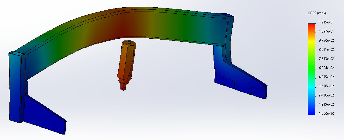
I also whipped up a simplified model of the router structure and put it through a very basic FEA simulation to ground my analysis method. I ended up with FEA numbers about +/-50% of the calculated values, so considering the assumptions I made just to get the CAD model to mesh, as well as the assumptions I’m making to get the hand calculations to work, that seems pretty close!
What constitutes an ‘acceptable’ deflection is hard to say but comparing deflection to run-out is a great starting point. When the pros think about deflection usually the machine is quite rigid but the tool itself is bending (because it is long or thin). Comparing the deflection of the tool to the chip load of the tool has a good correlation to tool wear, and likely to many other less quantifiable aspects of the cut as well. Keeping the deflection under 50% of chip load is a recommended rule of thumb, although in the case of deflection caused by the structure the tool life might not actually be impacted because it isn’t being cyclically loaded.
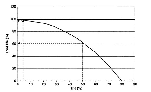
For the types of cuts I expect to be doing, typical chip loads will be between 0.003″ (aluminum) and 0.005″ (wood). Therefore, deflections over 0.04mm – 0.06mm are probably not that great. This means that the Y axis is 2 to 3 times sloppier than it should be!
The two fundamental ways to increase the stiffness of the Y axis are to change the material to something inherently stiffer (like steel) or change the geometry to increase the resistance to bending and torsion. Both options increase the mass of the gantry which has the negative impact of increasing the load on the motors during dynamic motions and the theoretical max speed of the Y axis.
I analyzed two options for increasing the Y axis stiffness. One was changing the main gantry beam from T slot extrusion to a similar (3″ x 6″ x 3/16″) rectangular steel tube. The other option is to bolt a 3″ x 3″ x 3/16″ aluminum square tube to the back of the T slot extrusion. The results of this comparison on the Y axis inertia, mass, and deflection are below.
| Al. T Slot Only | Steel Tube | Al. T Slot + Al Tube | |
|---|---|---|---|
| Area Inertia ( \(cm^4\) ) | 266 | 209 | 937 |
| Beam Mass ( \( kg \) ) | 16 | 26 | 22 |
| Bending Y Deflection ( \( mm \) ) | 0.07 | 0.03 | 0.02 |
| Torsional Y Deflection ( \( mm \) ) | 0.05 | 0.03 | 0.04 |
| Total Y Deflection ( \( mm \) ) | 0.12 | 0.06 | 0.06 |
Adding an aluminum box to the existing t slot tackles the bending deflection issue very efficiently but does not improve the torsional deflection nearly as well as the steel tube design. The overall deflection improvement between the two designs is fairly similar, putting them both at the very edge of acceptable deflections. Because the aluminum box design is lighter and probably easier for me to integrate into the design, I will likely choose to integrate that solution into the machine.
Other Sources of Deflection
If you compare the total X and Y axis input loads to the total X and Y axis deflection you get a ratio that approximates the ‘stiffness’ of the machine. Depending on the load case (orientation and magnitude), this machine has a structural stiffness of about 0.5 – 1.0 kgf/um (kilogram-force per micrometer). This value can be compared to other sources of stiffness loss to see if they are consequential or not.
Ball Nut
The stiffness of the ball nut is directly additive with other stiffnesses in a given axis. The stiffness of the ball nut is found in the catalog for the ball screws, and ranges from 18 kg/um on the Z axis (which is the smallest nut) up to 35 kg/um on the X axis (which is the largest nut). This is a full order of magnitude larger than the stiffness of the structure, so it is probably not important to consider it.
One caveat is that the preload within the ball nut drives this stiffness, and poor maintenance or other damage could drastically reduce the stiffness making it a driving factor in the overall machine stiffness!
Ball Screw
Load on the ball screw (both axial and torsional) can impact the assumption made about the relationship between motor position and tool position. Axial strain effectively changes the pitch of the screw while torsional strain effectively changes the lead.
Axial stiffness is simple to calculate using \( k=EA/L\) where E is the modulus of elasticity of the steel screw, A is the cross sectional area of the screw (maybe an average of the pitch diameter and root diameter?) and L is the length of screw being stretched.
Torsional stiffness is simple to calculate as well using the similar \( k_{\theta}=GJ/L \) where G is the modulus of rigidity (usually ~0.3 * E), J is the polar moment of inertia of the screw, and L is the length of the screw being twisted. However, to convert the torsional stiffness into linear stiffness it must be multiplied by the screw pitch twice (once for the force, again for the displacement) as \(k = k_{\theta} (2 \pi / p)^2\) where p is the screw pitch.
The axial stiffness of the screw is actually surprisingly low (although nearly an order of magnitude higher than the structural stiffness), while the torsional stiffness is plenty high.
| X Axis | Y Axis | Z Axis | |
|---|---|---|---|
| Axial Stiffness (\(kgf/um\)) | 3.6 | 8.0 | 6.3 |
| Torsional Stiffness in Axial Direction (\(kgf/um\)) | 18 | 24 | 70 |
Despite having the largest diameter, the overall length of the X axis screw results in a low axial stiffness that is likely a significant contributor to the overall stiffness of the machine in that direction. Fortunately, the structural stiffness is higher in the X axis direction than the Y axis direction so this one weak point will still not be the most significant factor for overall machine stiffness.
Motor Torque
With open loop stepping, a stepper motor can only apply a torque when there is a misalignment between the true position of the rotor (and more importantly its permanent magnets) and the equilibrium position of the rotor at a given time (as defined by the electromagnetic field of the stators). The torque output of the stepper motor increases as the angle of misalignment between the rotor and stator increases and is at its maximum value at a half step (1/200th of a rotation) from the equilibrium point. While not linear, this error can be thought of as a kind of ‘stiffness’ and compared to other stiffnesses of the axes to see if it is a significant contributor.
The torsional stiffness of the motor at any given speed can be approximated by the usable torque divided by the angular travel of half a step. Then, the torsional stiffness is converted to a linear stiffness using the same method as with the ball screw. At higher speeds (like when cutting wood) there is less usable torque in the motor and therefore a lower apparent stiffness. At lower speeds (like when cutting aluminum) there is more available torque in the motor which results in a higher apparent stiffness.
| X Axis | Y Axis | Z Axis | |
|---|---|---|---|
| High Speed Stiffness, 300IPM ( \(kgf/um\) ) | 2.2 | 4.4 | 14 |
| Low Speed Stiffness, 300IPM ( \(kgf/um\) ) | 5.8 | 12 | 14 |
Again, the X axis appears to be the weak spot. It has half of the available torque as the Y axis (which has dual motors) because it doesn’t need as much torque to accelerate (due to its lower stage mass). However, the lower torque does impact the apparent stiffness of the axis, especially at high travel rates (like what might be used for wood cutting). Luckily, heavy wood cutting likely uses a larger chip load than aluminum cutting, so the slight decrease in stiffness at high speeds will be offset by the decreased need for stiffness in the machine.
Other
There are plenty of other potential sources of deflection in the machine. Bending within the base of the machine itself could be incredibly significant, but tricks like adding a shear plate or tensioning cables could mitigate the issue.
Bending of the plate that connects the spindle mount to the Z axis bearing could be significant if it were modeled as one big plate in bending. In reality, the bearings hold one half of the plate rigid while the spindle mount holds the other half rigid. The small space in between could bend, but the angular deflection there is insignificant compared to the torsional deflection in the gantry.
Natural Frequency
The natural frequency of a spring/mass system is a balance of the restoring force of the spring (machine stiffness) with the resistive force of inertia (machine mass). The dominant resonant frequency of a machine is usually dependent on the lowest stiffness load direction – in this case, the Y axis.
When the machine deflects in the Y axis direction, the mass of the X axis carriage and everything mounted to it must move, and its inertia resists the movement. The equation for natural frequency is simply \( f = \sqrt{k/m} \div 2\pi \) where k is the stiffness, m is the mass, and f is the resulting frequency. For this machine, with a stiffness of 0.5 kgf/um and a mass of 35 kg, the natural frequency is about 60Hz.
This is an OK natural frequency. For controllability purposes you usually want the natural frequency to be a bit higher than the position control loop timing (usually ~10 – 100Hz) so that requirement is somewhat marginal.
Natural frequency can also work against you in a machine when the spindle speed happens to line up with a harmonic. A two flute endmill running at just over 1,800 RPM (or any integer multiple of this speed) will apply cyclic energy which could amplify any static deflections. Because the natural frequency calculation is imperfect, it is usually best to characterize the natural frequency of a machine after building it and keep that number in mind when selecting spindle speeds.
Conclusions
The only real surprise after doing these calculations was the low Y axis stiffness. The overall architecture for this router was so far based heavily on a combination of engineering intuition and looking at the avid CNC for guidance. For the most part the math checks out on most of the design decisions made by that company, but the Y axis stiffness issue is a curious difference.
Perhaps the linear rails themselves (which I ignored for the calculation) participate in the stiffness of the Y axis more than I assumed? Or the gantry risers act as more of a fixed constraint than I assumed? Either way, adding a box tube to the back of the gantry beam, where I need to put a cable track support anyway, is not very hard to package or expensive to add.