Building an electrical panel involves a ton of point-to-point wiring across a large quantity and variety of components. Even with the guidance of a detailed electrical diagram, the tedious work requires a lot of diligence to get right the first time. After the panel is wired and mounted it can take just as long to route, secure, and land all of the sensor, actuator, and power cables!
Panel Build
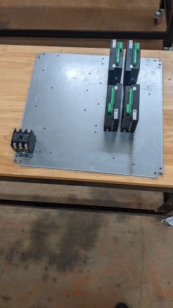
The first step in the electrical build is to work on the main panel. Most of the mounting and wiring can be done at a table instead of in the cramped enclosure. To start, the DIN rail, wire ducting, and panel-mounted components (contactor, motor drivers) need to be mounted to the panel with screws. Because there is a CAD layout of the panel, I was able to just follow a layout drawing and drill/tap all of the necessary holes in one go. After that, attaching everything was easy.
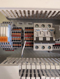
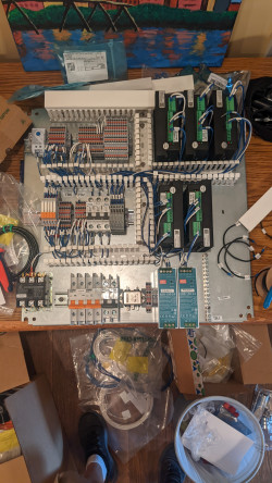
With the main components mounted the next step is to mount all of the DIN rail components. These are mainly distribution terminal blocks, but also include circuit breakers, power supplies, an AC filter, and some terminal-block-format components like relays and fuses. Once the components were mounted the individual connection wires were landed. Heat shrink labels were used to keep track of which wires go where (because the route itself is hidden inside the wire ducting). The goal of this stage is to connect all of the wires that exist completely within the electrical box, leaving only points where external cables (motors, sensors, power) land remaining unconnected.
Because several components mount directly to the enclosure, not all internal wires were connected at the panel level. One of the big benefits of using a more spacious box would be that large items mounted to the sides of the box in this project (motor power supplies and VFD) could be mounted directly to the panel wired at the panel level.
Enclosure Build
The electrical enclosure in this project has a ton of cutouts and holes that must be added in order to allow for component mounting and cable entry. The ideal way to use an industrial electrical box avoids any major modifications to the box itself by putting all cable entry points on the removable bottom plate and mounting all components to the panel. However, to save cost on the box itself (and at the expense of a lot of effort modifying the box!) this box is riddled with component mounting holes and cable entry cutouts on all sides.
To make lining everything up easier I cut out templates on posterboard in the laser cutter (similar to how I marked out most of the 3/8 plate in the mechanical build). This is especially important for cutouts that have associated mounting holes (like the HMI snorkel, main cable gland, and main disconnect). The holes were punched then cut out with either a drill bit, step drill, or hole saw (depending on the size). The rectangular cutouts were all removed with a jig saw. Cleaning out all of the chips and oil from the box afterwards was also very time consuming!
Some of the box-mounted components can be installed at this point. Filters, cable glands, and cord grips were easy to add. However, the main disconnect, VFD, and motor power supplies would have blocked inserting the panel, so they were not mounted yet.
Panel Mount and Cabling
Dropping the panel into the enclosure was fairly tricky because of the tight fit through the opening and large depth of the box, but it was easy to secure on the studs once I got it in. I mounted the motor power supplies and disconnect switch but held off on the VFD because it gets in the way of other components. There was plenty of internal AC connection wiring to do at this point between the newly added components and the panel. I also routed the main power cable into the box and connected it.
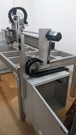
Next, I started running all of the cables along the frame and through the cable chains. In total, there are 10 sensor cables, 5 motor/spindle cables, and 4 encoder cables (more cables will be added later for probes and hoses for pneumatics). Most of the cables were pre-terminated and simply plugged in to their component with some kind of locking connector. The exception was all of the inductive proximity switches on which I had to install M8 plugs so they could connect with the M8 molded cables I had routed.
All of the cables were secured by zip ties throughout their run. There are zip tie mounts built in to each end of each cable chain, but I also installed fir tree zip tie mounts in several places (especially near limit switches to keep cables off of moving interfaces) and 3D printed zip tie mounts into the T slot extrusion.

All of these cables (with the exception of the spindle cable) enter the enclosure through a flexible gland on the right side of the box. The sensor cables run straight into the wire ducting behind the gland, while the motor cables stay outside of the duct and terminate directly into the drives to avoid any electrical noise issues.

I used three-tier terminal blocks (one tier each for power, common, and signal) for all of the sensor cables, despite their high price, because it makes the cabling process so much easier and more organized! of course each cable was labeled based on the electrical drawing, so it was easy to figure out where all of the wires went.

HMI Mount and Cabling
There are over 50 conductors across 10 cables routed between the main electrical enclosure and the screw terminals on the back of the integrated HMI/Controller. They all get snaked through the ‘snorkel’ and pop out into one of two wire ducts on the left side of the main enclosure.

The snorkel has some big holes in it to allow fat cables to pass through while still sealing against dust and water around the edges with big grommets. These holes were easier to make on the drill press than their counterparts (on the two boxes) were to make with a hand drill! I test fit the snorkel on the main enclosure early on before disconnecting it to assemble with the HMI enclosure separately.
The cables were all snaked through the snorkel and into the HMI enclosure before anything was landed to ensure that they were able to make the tight turns. Each wire was landed in the correct screw terminal, based on the electrical drawing. The cables were labeled on both ends so it would be easy to differentiate similar cables after the HMI assembly was installed on the main enclosure.

All of the cables were passed through the holes in the main enclosure when the snorkel was finally mounted! Initially they spilled out all over the floor, but one by one they were cut to length and landed on their appropriate terminals. Some run directly into the stepper drivers to send the pulse/direction signals, but most land in terminal blocks near the entry hole to distribute the signals to sensors, relays, and power.
With the HMI mounted the last of the cables were run and the machine is ready for commissioning! I am opting to leave the VFD out until the rest of the machine is running because it blocks access to a lot of things in the cabinet. It should be a quick install once I’m ready for it.
Time and Cost
I logged 31 hours of work on the electrical build. The majority of that time was wiring and cabling, with less than ten hours spent fabricating boxes, the panel, and the snorkel. This is significantly more than I expected, but in hindsight given that the component count of the electrical system (including individual wires and terminal blocks) is similar to the component count of the rest of the build combined it is no surprise that it took so long to complete. This build time would be even longer if I hadn’t splurged for things like pre-molded cables and fancy terminal blocks to make the build a bit easier.
The best option I can think of to ‘buy’ your way into more time savings is to dramatically change the size and format of the electrical enclosure. Using a console style enclosure would remove the complexity of the HMI ‘snorkel’ and associated cables, along with potentially being large enough to mount all of the large components directly to the panel instead of the side of the enclosure. Unfortunately, these enclosures start at around $1500, which is significantly more than the $250 I paid for the two enclosures and connecting tube in this design. However, used ones with old cutouts can be readily found at a significant discount on eBay if you are flexible on size and can pick it up directly from the seller (to avoid high freight charges on the heavy and bulky box).
The main electrical box assembly cost about $1450. The main driver was $450 for the three large motor power supplies. These power supplies are probably overkill and using different (lower inductance) motors would let you get away with only two, saving about $150. Other major contributors were $200 for the enclosure, $350 for terminal blocks and accessories, $100 for circuit breakers, $150 of hookup wire, and $100 for ventilation.
Although I already had many of the components available from a previous project, the total value of the motors, drivers, and their cabling was about $625. The cables were fairly cheap ($65) and the remainder of the cost was about half motors and half drivers (including the spare future A axis driver). Combined this is $2,125 for the comparable $3,100 ‘NEMA 34 control system’ for the Avid CNC.
Because I was able to cram the VFD into the main enclosure and am only using a cheap 1.5kW spindle, all of the costs related to the spindle sum up to just $400. This is much cheaper than the $2,000 spindle system and enclosure from Avid CNC, although their spindle operates at twice the power. In the future I hope to upgrade to an ATC spindle which will add a lot more cost and complexity.
The total cost of all 6 limit switches and 4 homing switches, along with their cables, was $175. Considering this is still less than the $285 sensor kit for the Avid CNC I have no regrets using separate limit switches and homing switches. The pre-molded cables and 3-tier terminal blocks made these some of the cheapest and easiest parts to install!
The integrated HMI+Controller, along with its mount and cabling, cost $525. The majority of this cost was the controller itself ($440, including pendant). This is more expensive than just using a $200 Mach4 license on an existing laptop to run an Avid CNC, but I think it is worth it to have a dedicated, rugged controller.
In total, the electrical portion of the project cost $3,175, compared to $5,580 with the avid CNC. The running cost for the entire project is now at $6,260, which is well below the $11,330 benchmark of the Avid CNC. At this point it is worth pointing out that these prices do not include the ~5% state sales tax that I have been paying ($310) and about $900 in shipping costs (half of which was from shipping large chunks of metal!). I’ve also probably spent around $1,000 on tools or high-volume, common consumables which will (hopefully!) be used in many more projects to come.
Of course, none of this means anything if the machine can’t perform as well as an Avid. Up next is the tiresome process of commissioning and testing. Hopefully the 92 build hours spent on this machine so far will pay off!


