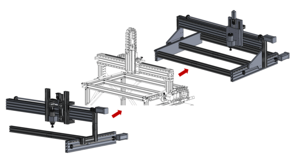
After first doing an initial exploratory design on your own you can be more prepared to analyze other designs solving similar problems because you have a better understanding of the challenges involved. The Avid CNC Pro4824 is the most similar commercial router to what I am attempting to design, and luckily their public build documentation provides a fantastic view into the details of their assembly process and mechanical design. After comparing their design decisions to my exploratory design I can continue to iterate on my own design, combining the best of both worlds.
Avid CNC Research
The Avid CNC is a great machine and their customers appear to be very happy with the performance. This machine is designed to support a variety of tools (real machine spindles, cheap routers, and plasma torches) as well as be modular and expandable (2, 4, and 8 foot Y axis versions are all available with a common gantry and control system). Because of these different requirements, compared to my more specific needs, it is not surprising that the Avid CNC is not a perfect fit for my use case. Still, there is plenty in common and plenty to be learned from the choices made by the Avid CNC engineers when designig their machine.
In the following sections I will step roughly through the mechanical design of the Avid CNC highlighting everything interesting, surprising, smart, or suspicious that I notice. These notes will serve as a critical reference while I iterate on my own design.
Base

- The adjustable feet are used to level the table, which is an important calibration step.
- The huge welded steel gussets definitely add a lot of stiffness to the legs, and are significantly cheaper than t-slot extrusion with the same size.
- I’m surprised that there is no diagonal bracing to prevent the table from going out of square. A big spoilboard might help with that, but people do use this machine without a spoilboard (especially with the rotary axis add-on) so I’m surprised that there is not more corner bracing.
- All of the t-slot extrusion is joined with anchor fasteners (including the legs), so all of the joints are preloaded and super stiff. My plan was to drill clearance holes through some extrusion and connect to threaded ends in other pieces, but that strategy doesn’t work out fully in 3-way corners.
- There is a dust cover over the linear rail, which definitely looks helpful, although less helpful than a bellows cover.
- The linear rail installation technique was clever, using a custom spacer to align each end of the rail to the edge of the extrusion. This is better than nothing, but the extrusion is obviously not very straight anyway so the benefits seem limited. A 3D printed alternative without the clamping might be just as effective.
- The mounting plates for the hard stop bumpers look fairly squishy. I guess as long as they don’t yield under worst case loads it should be fine. I’m not a fan of mounting limit switches (or their flags) on components that will get destroyed if the machine overruns its limits because it can lead to runaway motion on the machine.
- Obviously aligning the rack gear at this stage is super easy on the Avid CNC because the complexity was offloaded to the spring-tensioned belt-reducing spur gear assembly. I’ll need to investigate other CNC designs to compare my ball screw mounting options.
Gantry Riser

- The Y Axis bearings are located on a common machined lip on the main plate, keeping them perfectly aligned. Being mounted to the same plate makes that alignment very stiff, which should make it easier for the bearings to react moment loads as force couples.
- The same plate that mounts the bearings also has a flat reference edge on top for the gantry beam (along with a spacer) to rest on, keeping the gantry perpendicular to the Y axis.
- A thick 80mm x 80mm extrusion is used to stiffen the main plate. While it keeps the top of the plate (at the interface to the gantry beam) from bending, it does not appear to support bending right above the bearing mounts. This could be intentional to sacrifice stiffness in order to prevent the bearings from suffering a moment load in their ‘roll’ axis.
- The thin vertical plate seems supurflous. I do not understand what load case it helps the machine support. Because the thick plate on top of the 80mm x 80mm column supports the gantry beam in so many ways, my only guess is that the thin vertical plate helps prevent the gantry beam from rolling.
- All in all there appear to be a lot of different pieces involved in connecting the Y axis bearings to the gantry beam (5 when you include one in the gantry assembly too). My goal would be to reduce that to just one or two.
- It is important to note that the gantry beam is positively retained (does not reply on friction alone) in all directions except the one that is supported by gravity. This is probably a very active choice to keep the alignment from getting ruined from vibrations or crashes.
X Axis

- The Avid CNC manages to justify placing 20mm rails on a 120 mm lateral spacing (and what appears to be a 180 mm axial spacing based on the rail screw pitch) so I should be able to find a way to make the option close too. This definitely simplifies mounting and alignment.
- The top rail only is aligned to the outside face of the extrusion with the same jig that is used on the Y axis. It is very interesting to see that the rail extends past the extrusion and onto an aluminum plate on each end, which could be bad if those two parts were not perfectly flush.
- The X Axis end stop bumpers on the gantry appear to be just as flexible as the Y Axis ones. Also, they are a separate part from the various riser plates instead of being integrated (which is probably handy if the machine breaks the bumper mount plate and you want to replace it).
- The sensor flag is mounted to the back of gantry beam instead of adjacent to the bumper, which seems inconsistent and prevents the reuse of the same parts from the Y axis.
Gantry Carriage

- Interestingly, the gantry carriage plate does not appear to have a machined lip to keep all of the bearings aligned (or I just can’t see it). The lower rail is set in place by running the gantry along the rails, ensuring that the lower rail is parallel to the top rail if the bearings themselves are parallel to each other.
- Even though both a screw and a rack setup need some kind of ‘service arm’ to connect the gantry plate to the stuff on the top side of the gantry beam the load cases are different. While both setups must pass the axial load through to the gantry carriage plate (which requires some Z axis torque reaction), the moment load reaction torque for the rack setup is also around the Z axis, while the moment load reaction torque for the screw setup is around the X axis.
- While the connection between the two plates in the Avid CNC setup is flimsy in the X axis torque direction, it is quite strong in the direction that matters: Z axis torque. besides that, the joint really only needs to support the weight of the motor, and it doesn’t even need to do it with unreasonably high stiffness.
- This sort of connection would be terrible for a screw driven setup because reaction torque at the nut would just bend the joint. Making a similar component that can withstand both Z axis and X axis torque may require a 3D approach instead of the simple 2D plate in the Avid design.
Z Axis

- The Z Axis on the Avid CNC comes mostly as a premade kit so I can’t quite tell what the bearing and screw setup are.
- The base of the Z axis rises way above the gantry, with the motor (and presumably also the screw) mounted to the gantry carriage. The base does not extend at all below the gantry carriage, maximizing clearance.
- There is tons of dust protection on this stage (way more than the other two) which makes sense given how close it is to a constant hurricane of chips and dust.
- The Z axis motion stage is simply a T slot setup (although part of a unique and interesting U-shaped extrusion that would be really handy if publicly available). This makes it easy to mount whatever you want to the Z axis (Avid supports a variety of simples, as well as a plasma torch). The downside is that this flexibility adds one more later of thickness offsetting the tool from the Z and X axis bearings.
Spindle Mount

- The round spindle mount consists of three parts: The T slot mounting plate, the tramming plate, and the clamping plate. When combined with the t slot mounting surface of the Z axis carriage, this is four parts for one piece of relative motion (tramming adjustment). Obviously the Avid CNC is designed to flexibly mount many type of tools, but for a single purpose machine these four parts should probably just be two.
- Rotation around the X axis is accomplished by shimming the top or bottom edges of the plate. Shimming is an annoying guess and check method, but luckily tramming is not something that needs to be done very frequently.
- Rotation around the Y axis is accomplished by loosening the tramming plate from the T slot mounting plate so that it can pivot around the shoulder bolt in the top left corner. The eccentric bushing in the bottom right corner can be rotated to force the tramming plate to pivot one way or another before tightening the assembly back down.
Design Changes
Gantry Riser
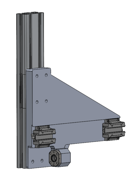
I really liked how the Avid CNC used a single plate to locate the Y Axis bearings parallel to each other, locate the gantry beam parallel to the Y Axis bearings, and set the height of the gantry beam equal on both sides. However, I did not like the four extra components that were used to bolt everything together. My goal is to use a single component to both stiffen the main plate and provide a secure mounting point to the gantry beam.
In this design, the bearings are mounted against a common reference lip which is machined parallel to the top edge (which butts against the gantry beam). What is unclear to me without doing real analysis is how much material I actually need in the diagonal space between the gantry beam and the front bearing (the Avid CNC had surprisingly little).
A single 40mm x 80mm t slot extrusion runs all the way from the top (where unshown clearance holes allow it to bolt into all eight threaded end holes of the gantry beam), down across the rear bearing, and ending at the bottom where it supports the ball nut.
In a previous design iteration the ball nut was rotated sideways and mounted directly to the t slot extrusion. While this allowed the plate to be made of 3/4″ stock instead of 1″ stock, the connection to the t slot extrusion was not very straightforward and the rotation of the nut requires the screw support bearings to be set off from their typical mounting point.
In this design the ball nut is firmly mounted to the same plate as everything else, and even has its own parallel reference feature. The reduced complexity of the ball screw support bearing mounting and ball nut mounting definitely make up for a slightly larger plate footprint and slightly thicker stock material.
X Axis Rail Spacing
Recall from a previous post that with the loading conditions and safety factors chosen it was very difficult to find a way to space the X axis rails just 120mm apart (the spacing for using slots on a 80mm x 160mm t slot extrusion). The driving load case was a machine crash while the motors were still at max torque, which would exert enough force on the X axis bearings to potentially damage them.
While artificially lowering the motor driver current was discussed as a way to prevent buckling on the Y axis, another options not considered was increasing the screw pitch. It was determined that screw pitches between 7.7mm and 25mm would be acceptable, and 10mm was chosen because it is more commonly available. 16mm (Y axis) and 20mm (X axis) pitches are still reasonably available and they reduce the axial load at stall by a directly proportional amount!
In the constant power regime of the motor nothing is changed (the stepper motor spins slower, but with more torque, to achieve the same speed and force on the axis as with the original pitch). However, the downside of this change is that the motor does not enter the constant power regime until a higher traverse rate. The effect on material removal is that low speed high force motions are more limited, which is obvious when you consider the change is proposed to minimize force at the lowest possible speed (stall).
An additional benefit of increasing the screw pitch is that is has the potential to increase the maximum rapid speed. Because inertial forces (the driving forces for a rapid motion) are so much more well known and constant than cutting forces, smaller factors of safety on motor power can be used without compromising performance (and the consequence of a position fault is significantly lower in rapid moves than cutting moves too). Additionally, screw whip becomes less of a concern when the motors don’t have to spin as fast to create the same linear motion.
The updated summary chart from the Axis Sizing post is now:
| Axis | X | Y | Z |
|---|---|---|---|
| Length (mm) | 1600 | 1000 | 400 |
| Pitch (mm) | 20 | 16 | 4 |
| Nominal Diameter (mm) | 20 | 16 | 12 |
| Root Diameter (mm) | 16.74 | 12.32 | 9.79 |
| Motor Configuration | 1 x NEMA 34 | 2 x NEMA 34 | 1 x NEMA 23 |
- Because the screw pitch for the X and Y axes is still under 25mm (calculated as the maximum for the constant power regime of the motor) the forces and speeds for the primary cutting load cases are still achievable.
- Because the loads decreased (although Y axis current limiting is no longer necessary) the buckling condition could not have worsened.
- Because the motor speeds decreased the screw whip condition could not have worsened.
Of course, after detailed design is complete all of the analyses will be repeated with final numbers, but this simple change is very likely to not have negative effects on machine capability. It also reduces the maximum individual bearing loads for a theoretical (and convenient) 120mm x 120mm bearing spacing from 47kN and 41 kN to 28kN and 25kN (two primary load cases, with FOS applied). This is below the 36.7kN needed to use 20mm rails, and is compatible with the desired rail layout!
Gantry Carriage
With the rails now spaced conveniently 120mm apart on the front face of the gantry beam, the X axis carriage is much easier to bring together with a simple plate.
Unlike the Avid CNC, I elected to include machined parallel reference features for mounting the bearings. This should make aligning the X axis rails and bearings much easier.
Instead of bolting on a second plate to the back of the main plate to interface with the ball nut I opted to use a piece of t slot extrusion. Clearance holes through the main plate allow a heavily preloaded joint connecting to the threaded holes in the end of the extrusion. By using all four holes the design should be able to react moment loads in all directions. Additionally, the same t slot extrusion can be used to connect to the cable track that will likely mount to the back side of the gantry beam.
Z Axis Carriage
The Z axis saw more iteration than any other part of the design. One major trade was if the bearing should live on the X axis or move with the Z axis (with the rails on the opposite side). The other major trade was if the relief for the ball screw system should be cut from the gantry side or the Z axis side. This impacted which components could be simple extrusions and which would need to be custom machined plates.


The first iteration of the design involved mounting the Z axis bearings to the gantry and the rails to the Z axis. The Z axis could then be made out of a piece of T slot extrusion with rails mounted in the slots like all other axes. This required a clearance channel to get machined in the center of the main gantry plate.
The biggest benefit of this approach was obviously that the Z axis structure could be a simple piece of t slot extrusion. The biggest downside of this design was that the Z axis bearings needed to be mounted very high up so that the spindle and tool could be raised above the bottom edge of the gantry for clearance moves. This arrangement puts a ton of extra forces through the Z axis bearings unnecessarily. Additionally, the Z axis is forced to support the weight of its driving stepper motor and ball screw in this configuration.


In the next iteration the rails were mounted to the main gantry carriage plate and the bearings were mounted to the moving Z axis structure. The Z axis could still be a simple piece of extrusion in this case (although a less common one, and without a solid story for how to connect the ball nut). With the Z axis all the way down (where it does most of its cutting) the bearings are also all the way down and mostly in line with the gantry, solving the problem from the previous design).
Mounting the rails to the main gantry carriage plate has the nice side effect of allowing them to rest against machined reference edges, which are controlled to be very perpendicular to similar reference edges on the other side of the plate for the X axis bearings. The downside of these features is that it requires machining on both sides of the plate.
Using a special thin extrusion with 40mm pitch features (but 5 slots on one side and 4 on the other) was very convenient for both mounting bearings with a 40mm hole pattern on one side and a variety of tools on the working side. I was especially happy with the horizontal slot layout because it would allow easy mounting of an engraving laser or distance sensor beside the spindle.
However, when looking towards the problem of tramming the spindle it seems like I would need an additional machined plate (much like the Avid CNC) to interface between my spindle clamp bracket and the t slot Z axis structure. At that point I might as well just make the entire Z axis structure a specialized machined plate. Additionally, the layout of this particular extrusion limited how far the spindle could stick out below the gantry carriage which could limit access to some part geometries.


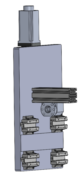
One final iteration was enough to make me happy with the notional design for the Z axis. The specialized extrusion making up the Z axis frame was replaced with another machined plate.
The clearance channel for the ball screw system was moved from the front of the gantry carriage plate to the back of the Z axis plate. This allows the gantry carriage plate to be machined from just one side, which is a manufacturability win.
The Z axis plate has locating features on the back for mounting the bearings parallel to each other, which helps make up for the lack of locating features on the Z axis rails. There is plenty of space on the front of the Z axis plate to incorporate features for tramming the spindle without adding more plates to the stackup.
The spindle mount can be extremely close to the bottom of the Z axis plate with this configuration, maximizing access to tricky part geometries. There is still space on the sides of the spindle for mounting other tool features, but that mounting will need to be designed and incorporated ahead of time instead of just scabbing something on to the t slots.
Full Design
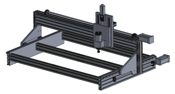
Overall I am very happy with the current iteration of the router design. I think it incorporates some important design considerations that were gleaned from the Avid CNC documentation while simplifying other parts of the machine based on my specific use case.
As detailed design work continues it is important to keep in mind that one of the major benefits of this design so far is its low custom part count. Of course a few little plates will need to pop up to complete the design (Y axis motor mounts, X axis bearing mounts) but the real challenge will be avoiding the need to add more and more parts just to implement hard stops, limit switches, cable management, tramming, and anything else required by the machine.


Hello,
Love the design. Did you ever build the unit. Would be interested in purchasing a set of plans if available.
Thanks,
Chuck
Chuck,
Thank you for the kind words! I did build the machine and all of the documentation for replicating it yourself is available for free. There are some posts near the end of the CNC router topic that highlight my experience commissioning the machine.
Detailed build guides and mechanical drawings are available on the documentation part of this website: https://burksbuilds.com/documentation/cnc-router/
Software and configuration information, along with 3D models (for the printed parts) are available on github: https://github.com/burksbuilds/CNC-Router
Let me know how it goes!
-Andrew