Cutting, drilling, and tapping 2D plate components from 3/8″ (10mm) and 3/4″ (20mm) Aluminum.
Stock
- 60 inch long: 3/8-inch (or 10mm) thick 6061-T6 Aluminum plate or bar, 4-inch (or 100mm) wide: for all motion platform components
- 10 inch long: 3/4-inch (or 20mm) thick 6061-T6 Aluminum plate or bar, 4-inch (or 100mm) wide: for Y axis ball nut mounts (consider using droppings from the 3/4-inch machined plates)
- 60 inch long: 3/8-inch (or 10mm) thick 6061-T6 Aluminum plate or bar, 4-inch (or 100mm) wide: for optional leg kit
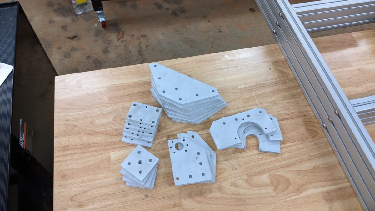
Components
CNCR-BASE ()
- 2 x CNCR-BASE-MM ()
- 2 x CNCR-BASE-HS ()
- 2 x CNCR-BBM () Y12-FREE Configuration
- 2 x CNCR-BBM () Y12-FIXED Configuration
CNCR-STAND ()
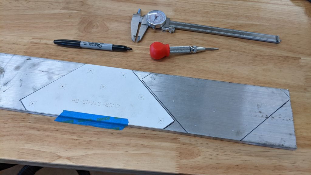
- 7 x CNCR-STAND-GP ()
- 4 x CNCR-STAND-FP ()
CNCR-GANT ()
- 2 x CNCR-GANT-BNM ()
- 1 x CNCR-BBM () X15-FREE Configuration
- 1 x CNCR-BBM () X15-FIXED Configuration
CNCR-CAR ()
- 1 x CNCR-CAR-BNM ()
- 1 x CNCR-CAR-MM ()
CNCR-SPIN ()
- 2 x CNCR-SPIN-HS ()
Tools
- Speed Square or Combo Square, optional calipers
- Scribe or fine-tip marker
- Center punch (preferably optical)
- Bandsaw, optionally also a miter saw (metal cutting blade)
- Drill or preferably Drill Press
- Jigsaw or Hole Saw (38mm or 1.5-inch), metal cutting
- File and/or deburring tool
- Tap Set (Metric)
- Standard Metric tap and clearance drill bit sizes
- Optional: Paper Templates (see CNCR-TEMPLATE-10MM)
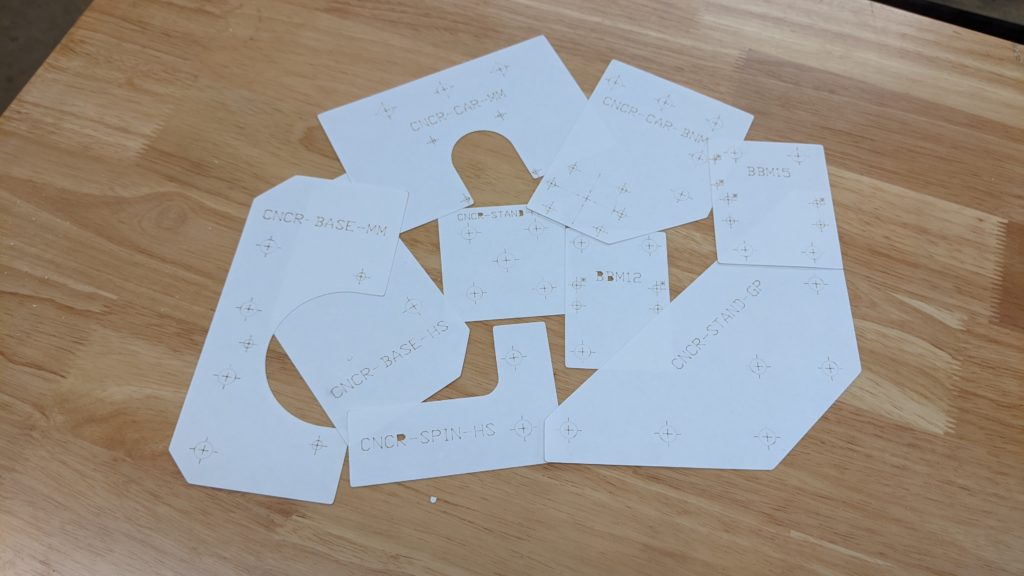
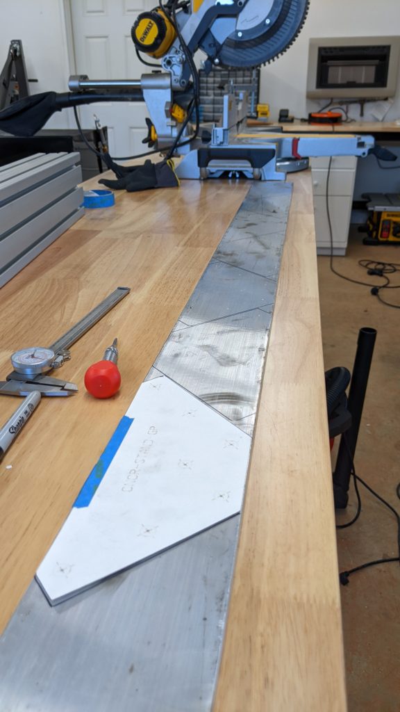
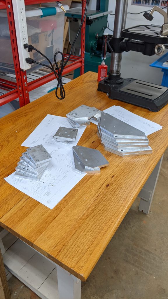
Layout
- Place templates on stock and secure with masking tape.
- Mark perimeter with fine-tip sharpie or scribe, using a straight edge as a guide.
- Mark hole centers with punch.
- Repeat with all parts, nesting to maximize material usage. Be mindful of saw kerf when spacing!
Cut
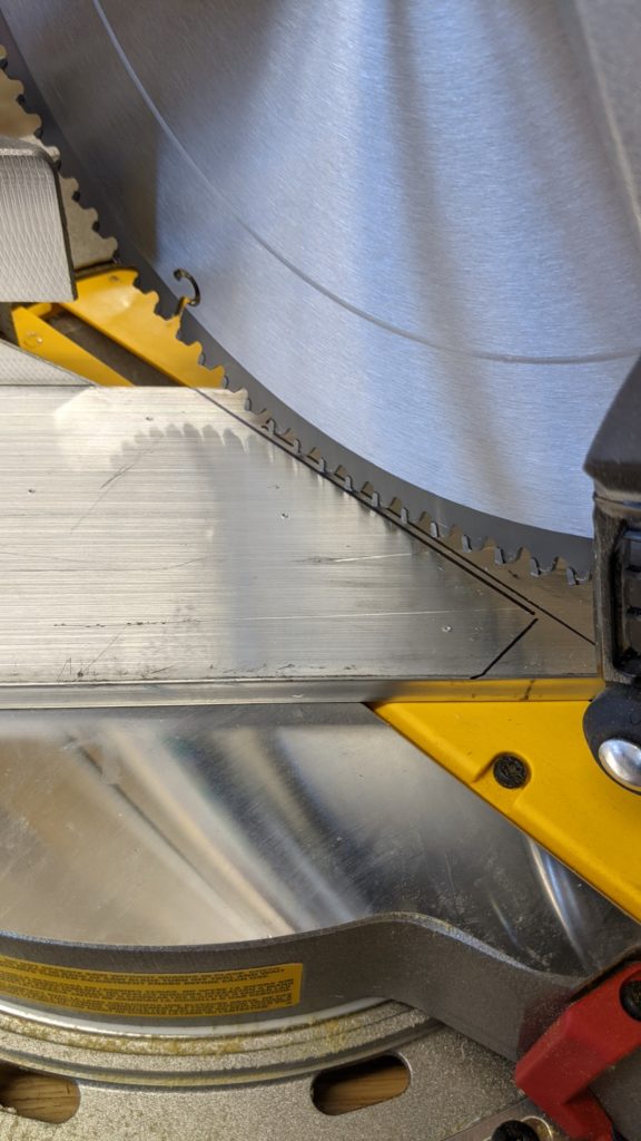
Straight cuts can be made on a miter saw with the appropriate blade.
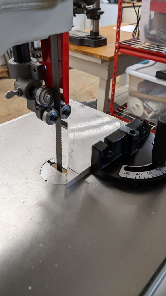
Clean-up or curved cuts can be made with a band saw.
Be sure to file/deburr all cut edges for safety.
Drill
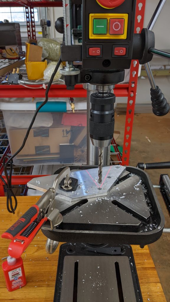
Consult the individual part drawings for each hole size. Hole perpendicularity is especially important for tapped holes, so use a drill press or be extra careful when drilling by hand.
Tap
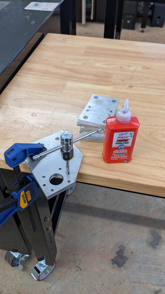
Consult the individual part drawings for each hole thread. Be sure to lubricate taps when threading and maintain perpendicularity as best as possible. For holes with a large aspect ratio (> 1:1) avoid power tapping with a hand drill and be sure to counter-rotate in order to break chips and clear the hole.
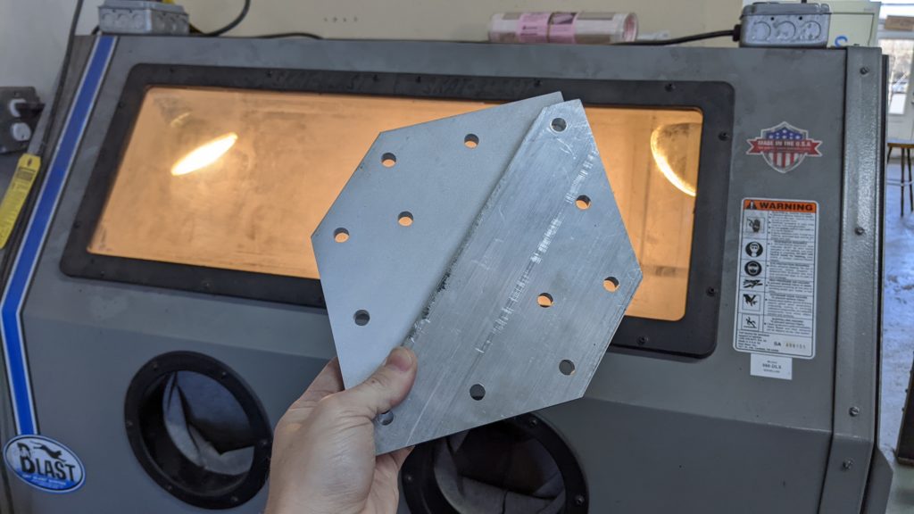
Clean
Wipe off all oil and clean out chips from threads. Sand blasting is optional, but it looks cool. Anodizing would be sweet but totally unnecessary.
Assemble
Several of the plates have a urethane strip adhered to their surface to act as a hard stop, and now is a great time to assemble the urethane onto the aluminum plates.
Start by cutting the shore 90A urethane strip (3/8″ or 10mm thick, 1″ or 25mm wide) to length for each section:
- 4 x 70mm CNCR-BUMP () Y Configuration
- 2 x 100mm CNCR-BUMP () X Configuration
- 4 x 40mm CNCR-BUMP () Z Configuration
The Y axis strips are placed on the top outer edges of the two CNCR-BASE-MM () plates and two CNCR-BASE-HS () plates.
The Z axis strips are placed on the outer flanges of the two CNCR-SPIN-HS () plates and the outer corners of the CNCR-CAR-MM () plate.