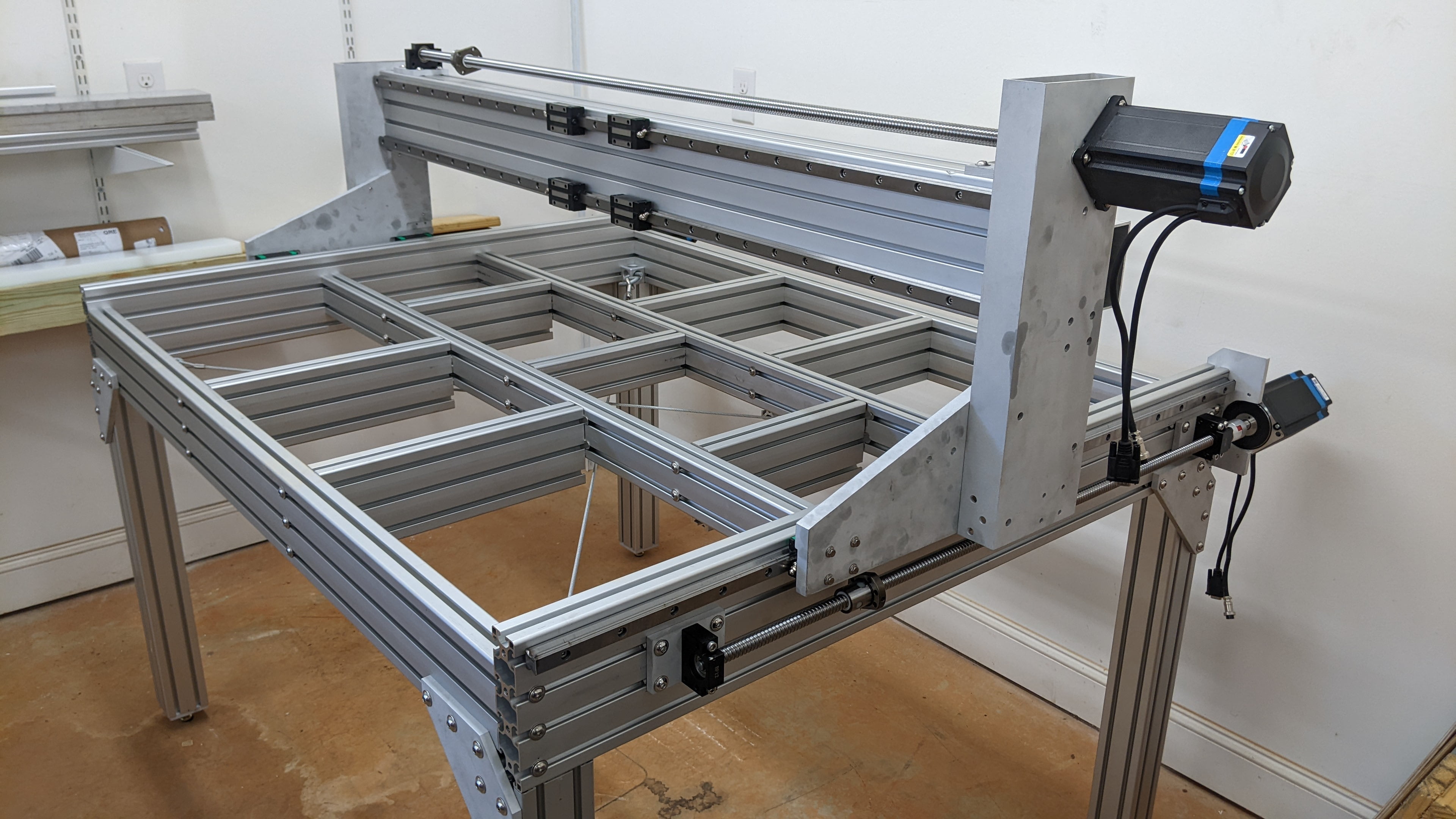
Bolting plates, extrusion, and tubes together, mounting and aligning rails and ball screws, to build CNCR-GANT ()
Components
Custom Parts
- 2 x CNCR-GANT-RP () (1 x FREE, 1 x CABLE configuration)
- 2 x CNCR-GANT-RT () (1 x FREE, 1 x CABLE configuration)
- 2 x CNCR-GANT-BNM ()
- 2 x CNCR-HSF () (XY configuration)
- 1 x CNCR-GANT-TSE-BEAM ()
- 1 x CNCR-GANT-ECM ()
- 1 x CNCR-GANT-TSE-ECM ()
- 1 x CNCR-BBM () X15-FREE Configuration
- 1 x CNCR-BBM () X15-FIXED Configuration
Purchased Parts
- 2 x Inductive Proximity Sensor (OMRON #TL-W5M or similar) [DWG#15]
- 2 x Box Tube End Cover, 2″ x 6″ or 50mm x 150mm (MoCap #RC2X6VBK1 or similar) [DWG#7]
- 2 x X Axis Ball Screw Kit (2010 x 1500mm) with ball nut, BK15/BF15 mounts, and motor coupling (14mm) [DWG#4,5,6,11,12]
- 2 x X Axis Linear Rail Kit (HGR20 x 1600mm) with 2 x HGH20-CA bearings each [DWG#14]
- 1 x X Axis Motor (NEMA 34) [DWG#4]
- 2 x Box Tube End Cover, 4″ x 4″ or 100mm x 100mm (McMaster #9565K49 or similar) [DWG#19]
- 1 x 4080 T-Slot End Cover (McMaster #5537T29 or similar) [DWG#20]
- 1 x X Axis Homing Switch (Panasonic #LS-TB-T with matching cable #CN-14A-R-C5) [DWG#13]
- 1 x X Axis Cable Chain (Igus #1500-068-100-14068-34PZA2-1166m) [DWG#16]
Hardware
See the Bill of Materials in the drawing for a full list of hardware. Hardware is referenced in this guide using the Item number from the bill of materials [DWG#XX] of the associated assembly drawing.
Column Assembly

Each side of the gantry is supported by a gantry column that connects the Y axis bearings to the gantry beam. These assemblies are very similar and are a mirrored version of each other (FREE and CABLE configuration).
Structure
The gantry column structure is primarily made up of the () bolted to the CNCR-GANT-RT () using M8 x 25mm cap screws [DWG#12]. To align the assembly, make sure that the ‘back’ face of the two parts are flush, then make the ‘bottom’ face of the two parts flush as a secondary reference. Use threadlocker on these screws to ensure a permanent joint.

Next, attach CNCR-GANT-BNM () to the assembly using M8x25mm cap screws [DWG#11]. This part should primarily be located against the tube (the mounting face) with secondary locating faces against the plate. Again, use threadlocker to ensure a permanent joint.
Bearings
The HGH20-CA bearings from CNCR-BASE () should be mounted to the machined pockets of each column plate. The upper lip of the machined pocked should be used to locate the bearings co-axially with each other. The grease fitting of each bearing should installed and face outward to ensure accessibility once the gantry is mounted.
Additional Components
On the CABLE side gantry column two limit switch sensors should be mounted using M3x12mm cap screws [DWG#13]. These are significantly more difficult to install once the column is mounted to the base.
CNCR-HSF () can be mounted now using M3x12mm cap screws [DWG#13], but can also be added later. The bottom lip of the machined pocket should be used as a reference to align the part.
Three M6 expanding rivet nuts [DWG#8] should be installed on the CABLE configuration of the column. Use a long M6 bolt to draw in the flexible anchor and secure the nut in place, then remove the temporary bolt. These rivet nuts will mount the X axis motor.
Beam Assembly
Structure
The gantry beam structure is made by bolting together CNCR-GANT-TSE-BEAM () and CNCR-GANT-ECM () using M8x12mm cap screws [DWG#31] and M8 t-nuts [DWG#29].


Align the bottom of both beams on a flat surface when bolting them together. Note that it may be easier to pre-thread the t-nuts onto the cap screws before sliding the entire square tube into the t-slots of the extrusion. Use threadlocker to ensure a permanent joint.
There are two M6 expanding rivet nuts [DWG#21] that must be installed on the box tube. Use a long M6 bolt to draw in the flexible anchor and secure the nut in place, then remove the temporary bolt. These rivet nuts will mount the X axis cable chain.
Rail Alignment
The linear rails are mounted to the top and bottom t-slots on the ‘front’ of the extrusion using M5x20mm cap screws [DWG#32] and M5 t-nuts [DWG#33]. Starting with the bottom rail, and in a similar technique to the rail mounting step of the base assembly, a dial indicator is used to position the rail one screw at a time. The bottom face of the T-slot extrusion should be used as the straightness reference for the alignment.

Once the bottom rail is in place the top rail should be mounted and aligned in a similar way, using the initial rail as the reference for the dial indicator. The spacing between the rails is critical, and the initial positioning should be set with calipers.
Ball Screw Mounting
Bolt both of the CNCR-BBM () plates to the top of the extrusion, using M8x20mm cap screws [DWG#28] and M8 t-nuts [DWG#29], but do not tighten the bolts fully because the plates will need to slide on the extrusion.
Bolt the ball screw bearing blocks, BK15 [DWG#9] and BF15 [DWG#10] to the bearing block mount plates using M6x40mm cap screws [DWG#27]. Use thread locker to ensure a permanent joint.
Mount the ball screw [DWG#11] between the bearing blocks, using the but built in to the BK15 block to secure the shaft. Keep track of the retaining ring for the BF15 side which will be installed later!

Additional Components
The Y axis cable chain mount, CNCR-GANT-TSE-ECM (), can be mounted now or at a later time. It is bolted in place using 2 x M8x40mm cap screws [DWG#25]. The exposed end of the extrusion should be capped with a press-on plastic cover [DWG#20]
The X axis limit switch flags can be mounted now or at a later time (they will definitely need to be adjusted during commissioning). To mount the flags, put an M8x20mm cap screw [DWG#28] through an M8x10mm spacer [DWG#35], then secure it to the T slot using an M8 t-nut [DWG#29].
The X axis homing switch [DWG#13] is installed onto the same plate that support the BK15 bearing block using M3x12mm cap screws [DWG#26].
Mounting the Beam
The gantry is assembled by first mounting each gantry column individually onto its rail, then by placing the entire gantry beam onto the gantry columns.
Columns
In order to slide the gantry columns onto the frame, the front hard stop plate CNCR-BASE-HS () along with the plate holding the BF12 bearing block must be removed.
Carefully slide the column onto the rail, ensuring that both bearings are secured on the rail. The bearings should slide freely but firmly on the rail, but if there is too much resistance it may be beneficial to loosen the bolts of the front bearing on the column assembly and re-tighten them while the bearings are both engaged with the rail.
Adjust the ball nut until it is in its most rearward position on the ball screw, oriented to line up with the mounting holes on the column and with the grease port facing outward. Push the column back until the ball nut on the ball screw engages with the clearance hole on the column. Fasten the ball nut to the column using M5x25mm cap screws [DWG#9] and threadlocker.
With the ball screw now at its most rearward position, tighten all of the screws on the BK mounting plate and motor mounting plate. This will lock in the proper relative position of the ball screw and bearings to prevent binding or internal stresses.
Replace the BF12 bearing block plate and secure the free end of the ball screw to the BF12 bearing block using the retaining clip that came with the BF12 bearing block. Manually rotate the ball screw to advance the column until the nut is as close to the BF12 bearing block as possible, then tighten all of the bolts to secure the BF12 plate to the t-slot extrusion.

Once both columns are mounted, manually rotate the ball screws to align the two columns in the Y axis as closely as possible.
Beam
With the help of a friend, lift the beam assembly up and place it between the columns. The bottom face of the t-slot extrusion of the beam should rest on the top face of the riser plates of the columns. The front face of the box tube of the beam should press against the back face of the box tube of each column.
Using M8x25mm cap screws [DWG#22] (4 on each side) secure the gantry beam onto the columns. Keep pressure on the beam to ensure that the two reference faces mentioned above remain in contact during assembly. Do not use threadlocker at this point, because the joints may be shimmed at a future stage. You may need to use pliers to position the bolts in place before fastening them.

Other Components
The X axis cable chain [DWG#16] is bolted in place using 2 x M6x16mm flat screws [DWG#30]. It can be connected now, or at a later time when the gantry carriage is installed.
The X axis motor is bolted onto the CABLE side column using M6x20 cap screws [DWG#23]. Assemble the shaft adapter [DWG#5,6,12] and use it to connect the ball screw shaft to the motor shaft.
The gantry column box tube covers [DWG#7] should be installed now that access to the inside of the tubes is no longer required. The gantry beam box tube covers [DWG#19] can also be installed at this point. Use a mallet to tap them into place.